113
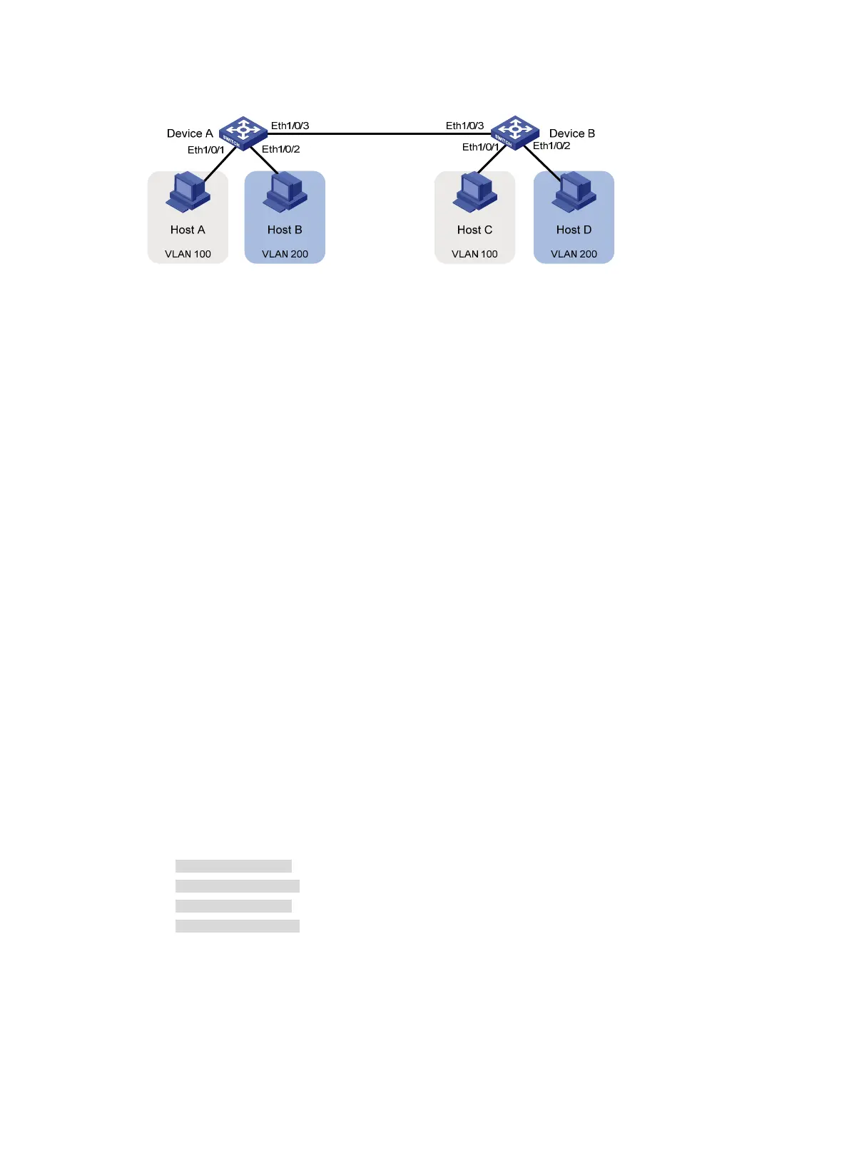
Figure 35 Network diagram
Configuration procedure
1. Configure Device A:
# Create VLAN 100, and assign port Ethernet 1/0/1 to VLAN 100.
<DeviceA> system-view
[DeviceA] vlan 100
[DeviceA-vlan100] port ethernet 1/0/1
[DeviceA-vlan100] quit
# Create VLAN 200, and assign port Ethernet 1/0/2 to VLAN 200.
[DeviceA] vlan 200
[DeviceA-vlan200] port ethernet 1/0/2
[DeviceA-vlan200] quit
# Configure port Ethernet 1/0/3 as a trunk port, and assign it to VLANs 100 and 200, to enable
Ethernet 1/0/3 to forward traffic of VLANs 100 and 200 to Device B.
[DeviceA] interface ethernet 1/0/3
[DeviceA-Ethernet1/0/3] port link-type trunk
[DeviceA-Ethernet1/0/3] port trunk permit vlan 100 200
Please wait... Done.
2. Configure Device B as you configure Device A.
Verifying the configurations
1. Determine whether the configuration is successful by displaying relevant VLAN information.
# Display information about VLANs 100 and 200 on Device A.
[DeviceA-Ethernet1/0/3] display vlan 100
VLAN ID: 100
VLAN Type: static
Route Interface: not configured
Description: VLAN 0100
Name: VLAN 0100
Tagged Ports:
Ethernet1/0/3
Untagged Ports:
Ethernet1/0/1
[DeviceA-Ethernet1/0/3] display vlan 200
VLAN ID: 200
VLAN Type: static
Route Interface: not configured
Description: VLAN 0200
Name: VLAN 0200
 Loading...