42
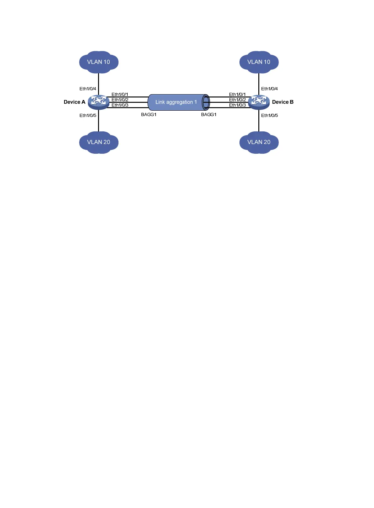
Figure 10 Network diagram
Configuration procedure
1. Configure Device A:
# Create VLAN 10, and assign port Ethernet 1/0/4 to VLAN 10.
<DeviceA> system-view
[DeviceA] vlan 10
[DeviceA-vlan10] port ethernet 1/0/4
[DeviceA-vlan10] quit
# Create VLAN 20, and assign port Ethernet 1/0/5 to VLAN 20.
[DeviceA] vlan 20
[DeviceA-vlan20] port ethernet 1/0/5
[DeviceA-vlan20] quit
# Create Layer 2 aggregate interface Bridge-Aggregation 1.
[DeviceA] interface bridge-aggregation 1
[DeviceA-Bridge-Aggregation1] quit
# Assign ports Ethernet 1/0/1 through Ethernet 1/0/3 to link aggregation group 1.
[DeviceA] interface ethernet 1/0/1
[DeviceA-Ethernet1/0/1] port link-aggregation group 1
[DeviceA-Ethernet1/0/1] quit
[DeviceA] interface ethernet 1/0/2
[DeviceA-Ethernet1/0/2] port link-aggregation group 1
[DeviceA-Ethernet1/0/2] quit
[DeviceA] interface ethernet 1/0/3
[DeviceA-Ethernet1/0/3] port link-aggregation group 1
[DeviceA-Ethernet1/0/3] quit
# Configure Layer 2 aggregate interface Bridge-Aggregation 1 as a trunk port and assign it to
VLANs 10 and 20.
[DeviceA] interface bridge-aggregation 1
[DeviceA-Bridge-Aggregation1] port link-type trunk
[DeviceA-Bridge-Aggregation1] port trunk permit vlan 10 20
Please wait... Done.
Configuring Ethernet1/0/1... Done.
Configuring Ethernet1/0/2... Done.
Configuring Ethernet1/0/3... Done.
 Loading...