Single-ended TDR Measurements
Single-ended TDR Features
7-6
Excess L/C
The most common discontinuities seen on an TDR waveform are due to series
inductances or shunt capacitances. Some causes of series inductances are wire
bonds or traces that are too narrow. Some causes of shunt capacitance are wire
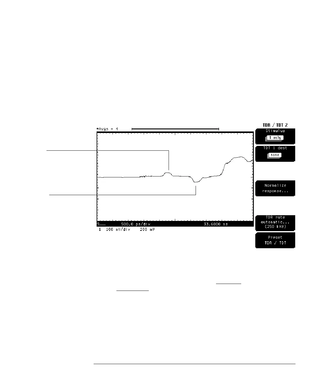
bond pads or traces that are too wide. A series inductance is seen as a positive
bump while a shunt capacitance is seen as a negative bump in the oscilloscope
waveform (Figure 7-1).
Figure 7-1
Series Inductance and Shunt Capacitance
A feature called Excess L/C can be used to calculate the excess inductance (L)
or excess capacitance (C) between the x and + markers. The Excess L/C feature
is enabled by setting the Marker
Mode
menu to TDR/TDT and the
Reference
menu to ref plane
. If a reference plane has been established by selecting
the
Establish normalization & ref plane
in the TDR/TDT Setup
Normalize response...
menu, then a readout appears at the bottom of the screen called "Excess L/C.”
The excess L or C in this case is defined as the equivalent amount of series L
or shunt C that would cause a discontinuity with equal area to the discontinuity
between the x and + markers.
Inductance
Capacitance