Single-ended TDR Measurements
Measuring Transmission Line Impedance
7-22
11 At the bottom of the display, read the number of volts for the narrow
trace discontinuity (Figure 7-13).
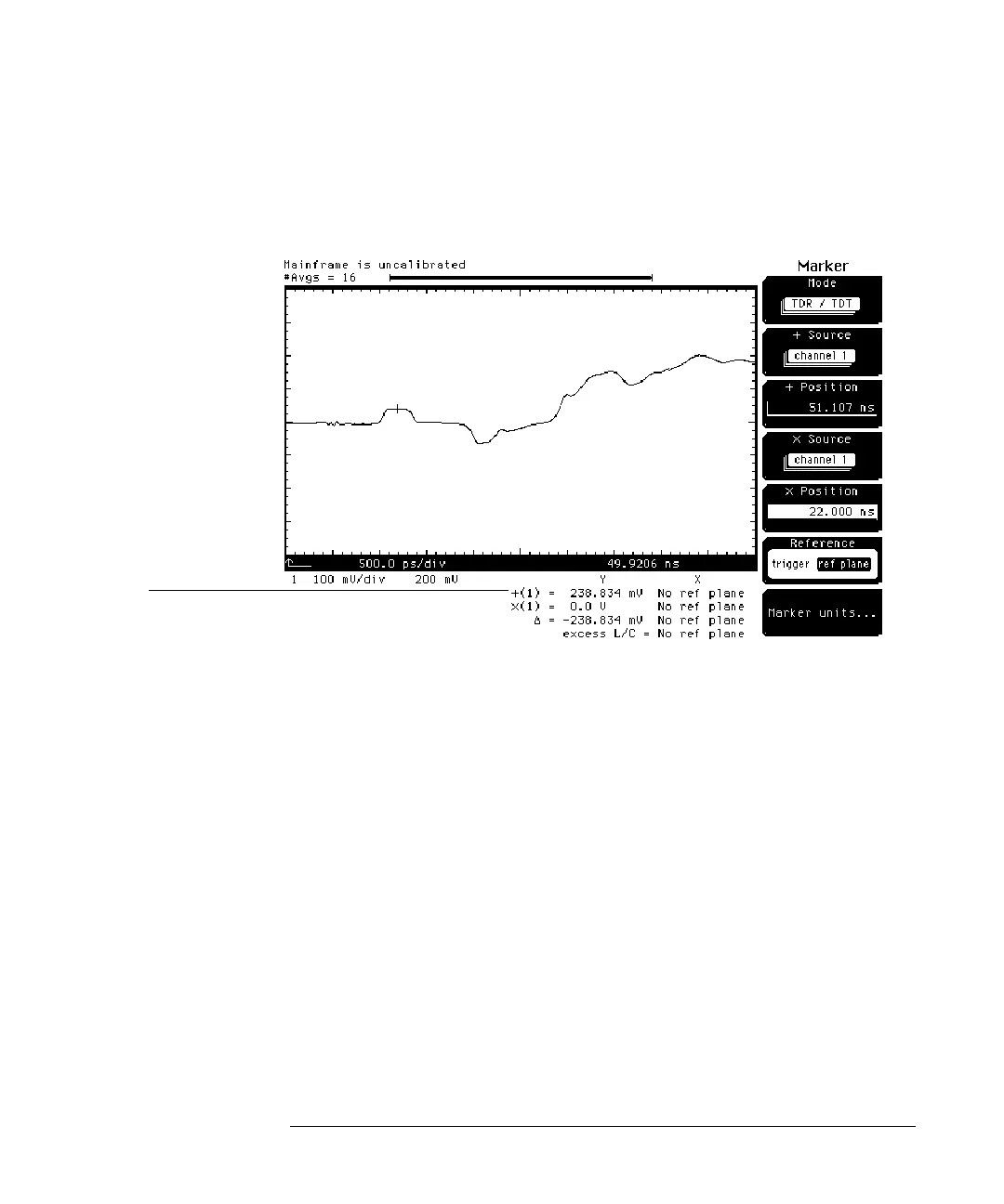
Figure 7-13
In this case, the voltage, vd1, is approximately equal to 238.834 mV.
Substituting and solving for p we have:
therefore,
Instead of calculating the impedance from the measured voltage, we can have
the oscilloscope calculate the impedance. Before we can do this we must first
establish normalization and the reference plane at the end of the cable
connected to the demo board. This requires a very accurate low reflection 26.5
GHz 50 ohm load, such as the HP 909D.
1 Press the TDR/TDT Setup key.
2 Press
Normalize response . . .
softkey.
3 Disconnect the cable from the demo board.
4 Press the
Establish normalization & ref plane
softkey.
Narrow Trace
Voltage
p
238.834 200–
200
---------------------------------- 0. 1 9 4 1 7==
Z 50Ω
1 0.19417+
1 0.19417–
----------------------------
× 74.09565Ω==