Single-ended TDR Measurements
Measuring Excess L/C
7-36
1 Change the
+ Position
until + marker is on the right side of the negative
bump.
2 Change the
X Position
until the X marker is on the left side of the negative
bump.
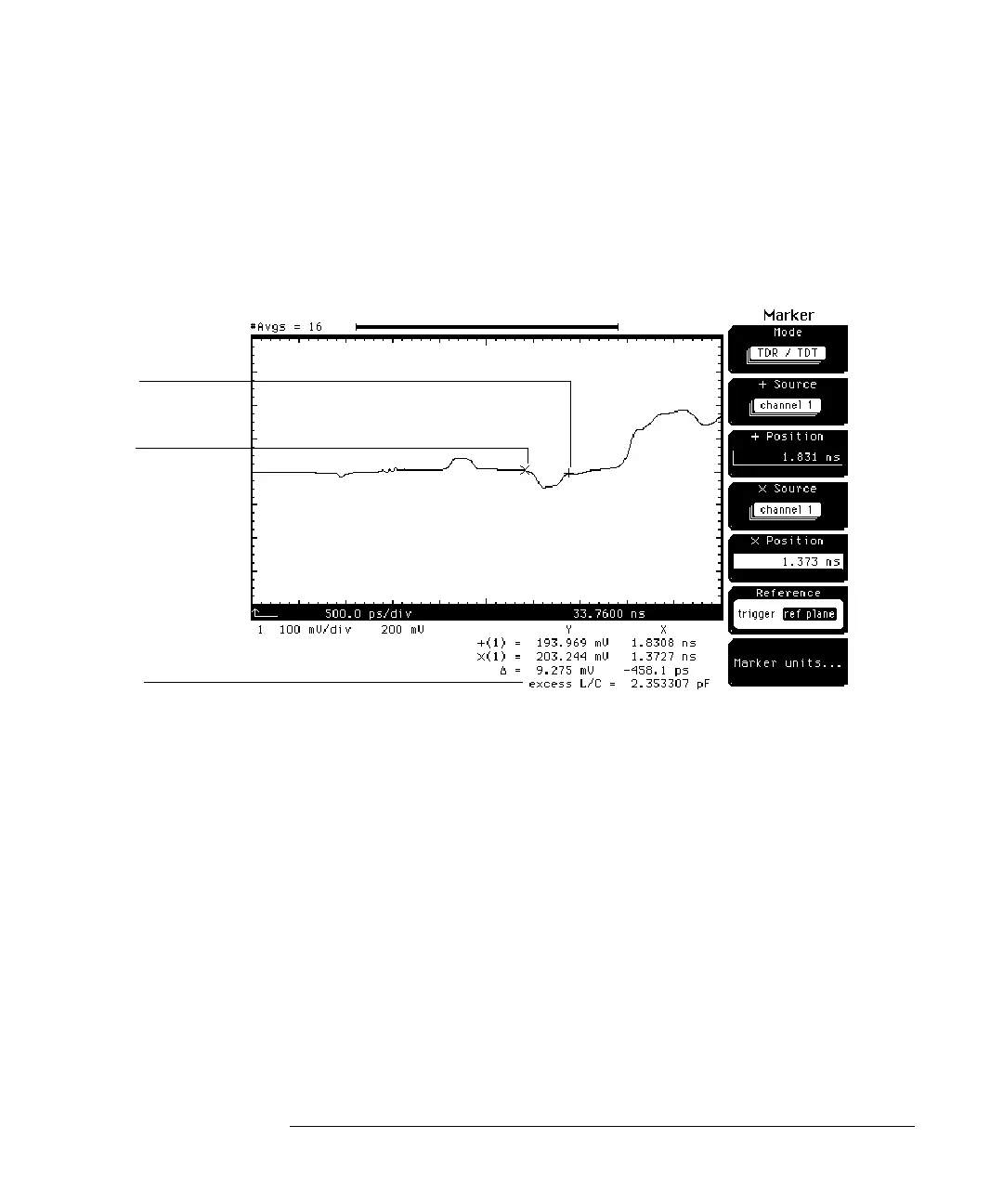
Figure 7-23
The excess L/C of the negative bump is 2.353307 pF. The negative bump is not
as well defined (or as square) as the positive bump. This is due to the filtering
effect that the positive bump (inductive section) has on the negative bump
(capacitive section). For example, the reflections off the capacitive section
have to pass back through the inductive section before it can be viewed. To get
a more accurate measure of the capacitive section, connect the cable to the
single transmission line closer to the wide trace.
+ Marker
X Marker
Excess L/C