Differential TDR Measurements
Measuring Differential and Common Mode Impedance
8-11
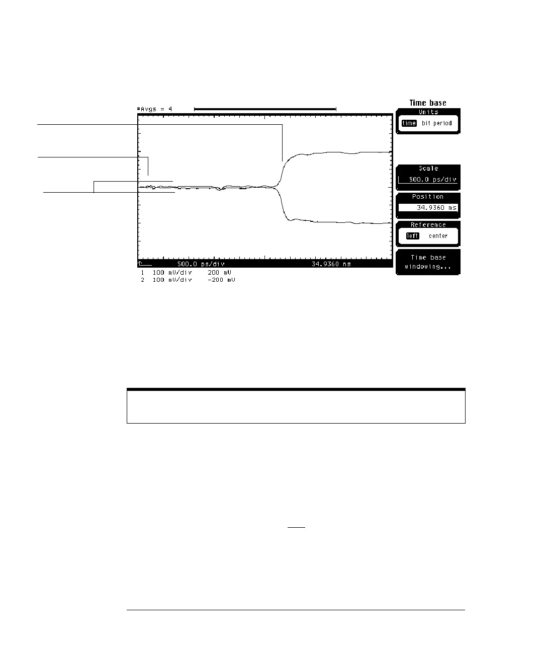
Figure 8-6
The portion of the waveforms starting at the left-hand of the display is where
the cables are connected to the differential line. The positive and negative going
steps are the reflected steps from the end of the differential line. The waveform
separation seen is due to the difference in impedance along the differential line.
The differential mode impedance for two 50 ohm uncoupled lines is 100 ohms.
To verify which part of the waveform represents a certain part of the differential
line, touch the differential line with your finger. A bump in the waveform will
appear which represents the location of your finger along the differential line.
To measure the impedance of the differential line, use the following procedure.
1 Press SETUP Channel 1/3 key.
2 Press the
Alternate scale . . .
softkey.
3 Press the
Units
softkey and select Ohm.
4 Press the
Enter
softkey.
5 Press the
Done
softkey.
6 Press
SETUP Channel 2/4 key.
Before performing the next step, be sure to wear a grounding strap connected to
the mainframe ground.
Waveform
separation
Start of
differential line
Reflected step at the
end of differential line