Differential TDR Measurements
Making Differential TDT Measurements
8-25
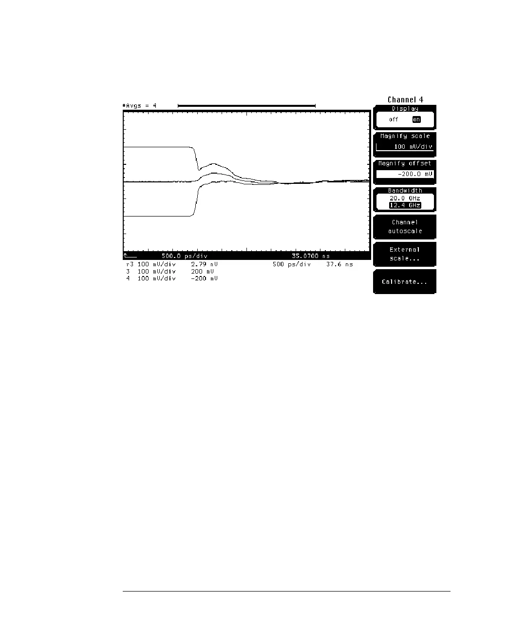
Figure 8-18
This situation might occur on a clock distribution line of a digital PC board where
an input pin of a gate connected one side of line has an excess capacitance of
10 pF. The gate receiving the differential signal might produce a glitch or might
not switch properly.
Even though the extra capacitance was connected to only one of the differential
lines, the waveforms for both differential lines were affected. This shows that
the differential lines are coupled. If the differential lines were separated by a
greater distance, the capacitive load would only affect one side and not both
sides of the differential line.
While both differential lines show the effects of the capacitive load, the
differential line connected to the capacitive line shows the most change.
Knowing this allows you to find the differential line which has the problem.