TDR Fundamentals
Step Reflection Testing
9-17
Figure 9-14
A 50
Ω
TDR System Testing a 50
Ω
Line Terminated With an Open Circuit.
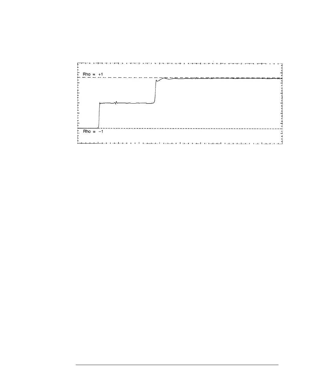
In Figure 9-15 this was not the case. Here the source impedance of the step
generator is 50 Ω and the line impedance is 75 Ω. The jump from a 50 Ω to a
75 Ω cable is evident and follows TDR rules. But the step from the 75 Ω cable
to the open circuit does not. Instead of jumping to a +1 reflection coefficient
for an open circuit, the trace actually exceeds that value.
The 50 Ω to 75 Ω mis-match caused the reflected wave returning from the open
circuit to be re-reflected at the source, thus launching a second incident wave
down the line. This second wave travels back to the monitoring point. The
second reflected wave, in turn, launches a third incident wave, down the line.
This process continues indefinitely, but unless the reflection coefficient at each
end is equal to ±1, the reflections decrease in magnitude and only the first few
are noticeable.