TDR Fundamentals
Step Reflection Testing
9-18
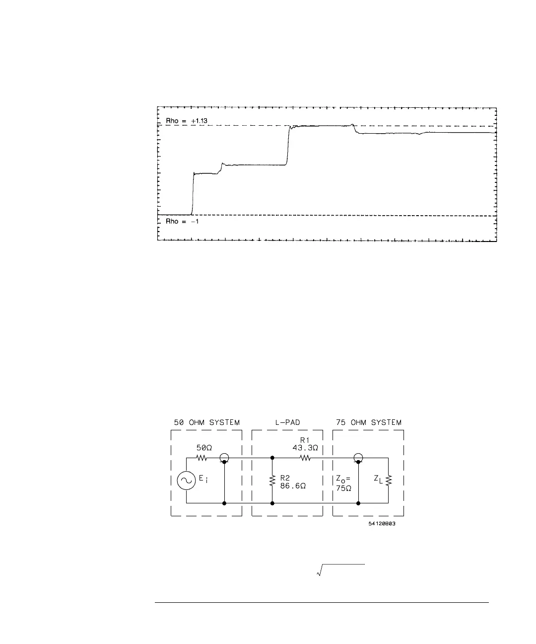
Figure 9-15
A 50
Ω
TDR System Testing a 75
Ω
Line Terminated With an Open Circuit Yields a Display That is
More Difficult to Interpret
Balun For measurements of transmission lines in the 200 Ω to 300 Ω
region, a balun is the best solution. A good balun will permit a 200 Ω line
to be tested without the danger of re-reflections from the 50 Ω source. A
broadband balun should be used so that the incident step is not appreciably
affected by sag or loss of risetime.
Matching L-Pad To completely eliminate the effect of multiple
reflections in a non 50 Ω system, use a simple matching L-pad. Refer to
Figure 9-16 and Figure 9-17.
Figure 9-16
L-Pad Matching 50
Ω
Source to 75
Ω
System Impedance
for Z
o
> 50 Ω:
Resistance in series with Z
o
,
R
1
Z
o
Z
o
50–
()
=