TDR Fundamentals
Instrument Configuration
9-21
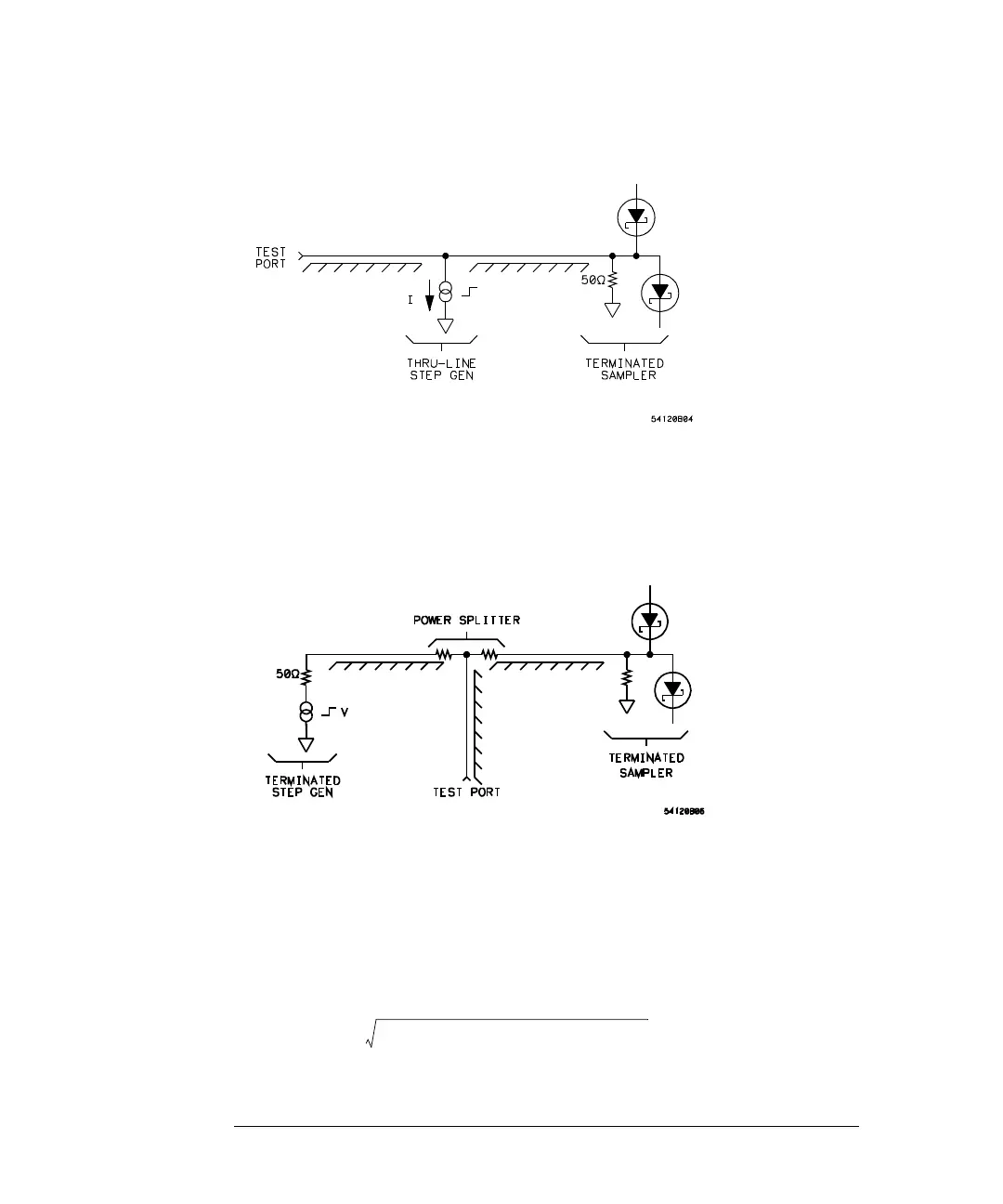
Figure 9-19
The terminated sampler, terminated step generator, and power splitter
architecture in Figure 9-20 is usable but is typically not used because both the
incident and reflected step are attenuated when they pass through the power
splitter. This decreases the system signal-to-noise ratio.
Figure 9-20
Risetime and Distance Resolution
The examples shown so far have assumed that the TDR step has zero risetime.
Practical TDR systems have a finite risetime for both the step generator and the
sampler. The effect of the finite risetime of the TDR system is to low-pass filter
the ideal (zero risetime) response of a given discontinuity with a filter that has
a risetime equal to the combined risetime of the step generator, sampler, and
test setup which is approximated by:
t
r
system
t
r
step gen
()
2
t
r
sampler
()
2
test setup
()
2
++
≅