Transmission Line Theory Applied to Digital Systems
Transmission Line Design
11-4
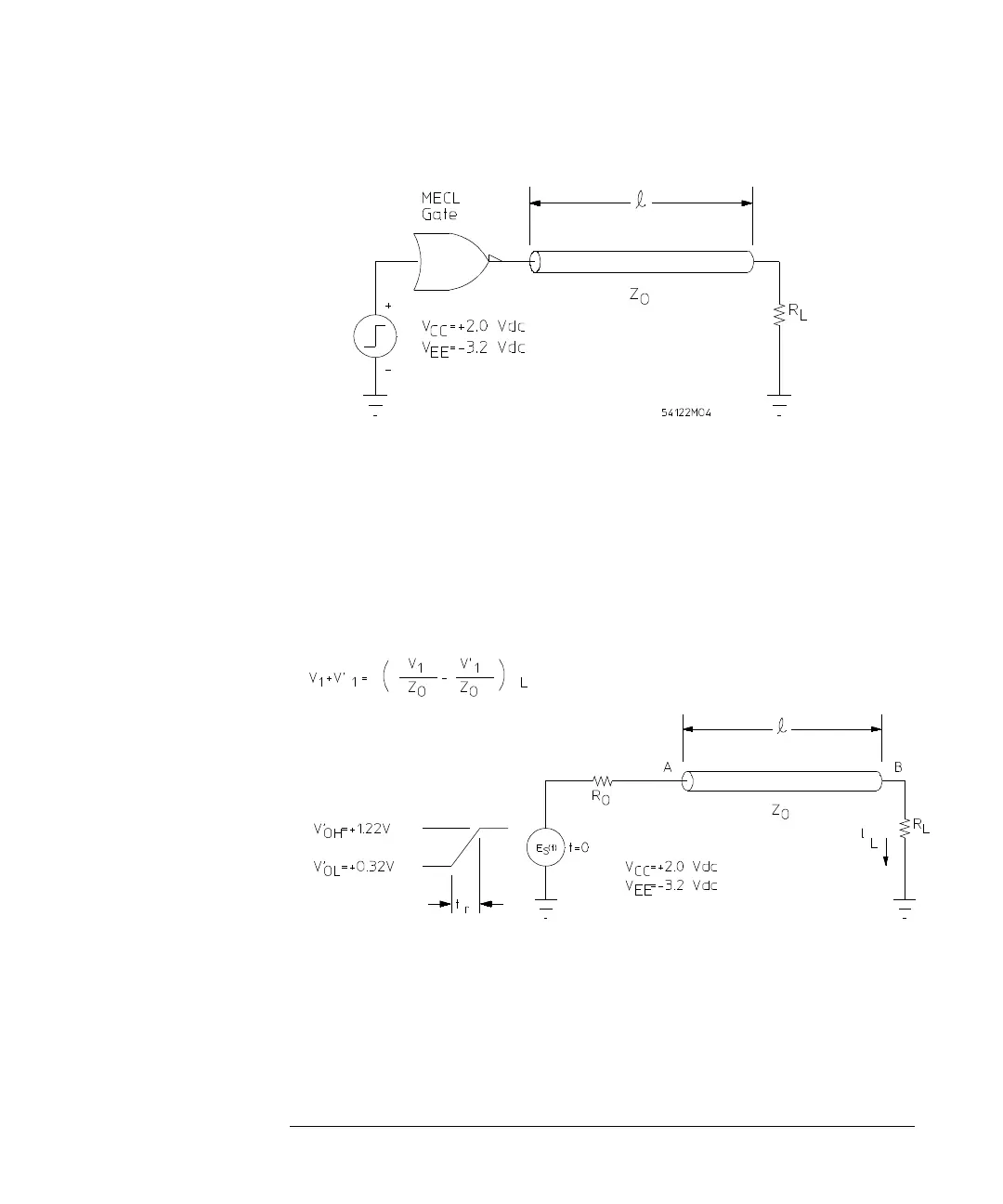
Figure 11-2
MECL Gate Driving a Transmission Line
The circuit of Figure 11-2 can be redrawn as shown in Figure 11-3 to include
the equivalent circuit of the MECL gate. The resistor, R
o
, is the output source
impedance (for MECL 10K/10KH it is 7 Ω, and MECL III it is 5 Ω). According
to theory, the risetime of the driving voltage source is not affected by the
capacitance of the transmission line. Except for skin effect and dielectric losses,
the signal will remain undistorted until it reaches the load.
Figure 11-3
Equivalent MECL Gate Output, Driving a Transmission Line
The equation representing the voltage waveform going down the line as a
function of distance and time can be written as:
(1)
R
v
1
xt
(,)
v
A
t
()
ut xt
pd
–
()•
, for t <
T
D
=