Transmission Line Theory Applied to Digital Systems
Microstrip Transmission Line Techniques Evaluated Using TDR Measurements
11-24
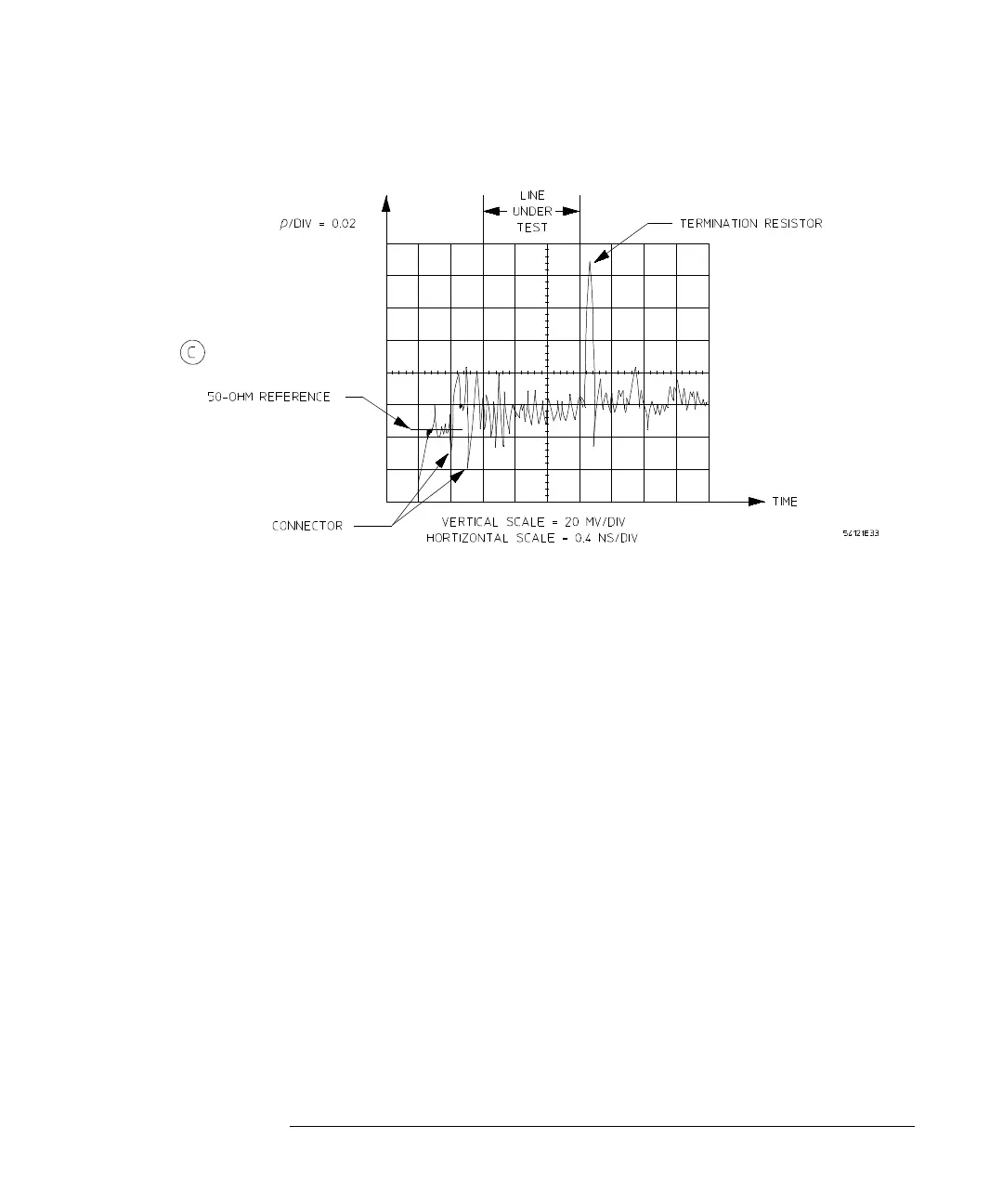
Figure 11-10
TDR Determination of Line Characteristic Impedance (Continued)
The reflected voltage due to the connector is ±40 mV. The line reflects a voltage
of ±25 mV due to variations in the characteristic impedance of the line. The
reflection of 88 mV shown for the termination resistor (ρ = 0.088) is due to the
inductance of the resistor. It can be calculated that the inductance of the
resistor is less than 0.9 nH.
In these experiments, the input waveform comes from a generator which has a
risetime of 28 ps. There is some attenuation of the signal noticeable as it reaches
the termination resistor (t
r
= 80 ps at the load). When driving the line with a
MECL III gate with a risetime of 1 ns, the reflection due to the inductance of
the resistor would be much less (about 10 mV).
TDR Example 2
An equation can be derived to determine the maximum reflection voltage due
to the inductance of the resistor leads. The circuit shown in will be used in the
derivation.
The reflection coefficient at the load is:
(16)
ρ
L
s
()
Z
L
Z
o
–
Z
L
Z
o
+
------------------
R
L
sL
+
()
Z
o
–
R
L
sL
+
()
Z
o
+
------------------------------------
s
R
L
Z
o
–
L
------------------+
s
R
L
Z
o
+
L
------------------+
---------------------------== =
 Loading...


