Transmission Line Theory Applied to Digital Systems
Microstrip Transmission Line Techniques Evaluated Using TDR Measurements
11-25
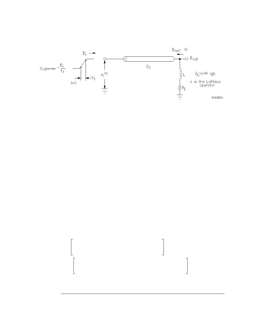
Figure 11-11
Circuit for Determining the Maximum Reflected Voltage Due to the Inductance of the Resistor Leads
where s is the LaPlace operator for jω. The driving voltage will be represented
as:
(17)
where u(t) is a step function occurring at t = 0. Taking the LaPlace transform
of equation 17 gives:
(18)
The reflected voltage at the load is then the product of the driving voltage and
the reflection coefficient (both in the transformed plane):
(19)
Taking the inverse LaPlace transform yields:
(20)
e
i
t
()
mtu t
()
mt T
1
–
()
ut T
1
–
()
–=
E
i
s
()
m
s
2
---- 1
e
T
1
s
–
–
()
=
E
i
s
()
E
i
s
()ρ
L
s
()
s
R
L
Z
o
–
L
------------------+
s
2
s
R
L
Z
o
+
L
------------------+
--------------------------------------
m
•
1
e
T
1
–
()
s
–
()
==
E
ref
1
t
()
2
Z
o
L
R
L
Z
o
+
()
2
--------------------------
R
L
Z
o
–
R
L
Z
o
+
------------------
t
2
Z
o
L
R
L
Z
o
+
()
2
--------------------------
e
R
L
Z
o
+
()
t
L
-------------------------–
–+
mu t
()
2
Z
o
L
R
L
Z
o
+
()
2
--------------------------
R
L
Z
o
–
R
L
Z
o
+
------------------
tT
1
–
()
2
Z
o
L
R
L
Z
o
+
()
2
--------------------------
e
R
L
Z
o
+
()
tT
1
–
()
L
-----------------------------------------–
–+
mu t T
1
–
()
–=
 Loading...


