Model
5528A
Angular Measurements
6-6
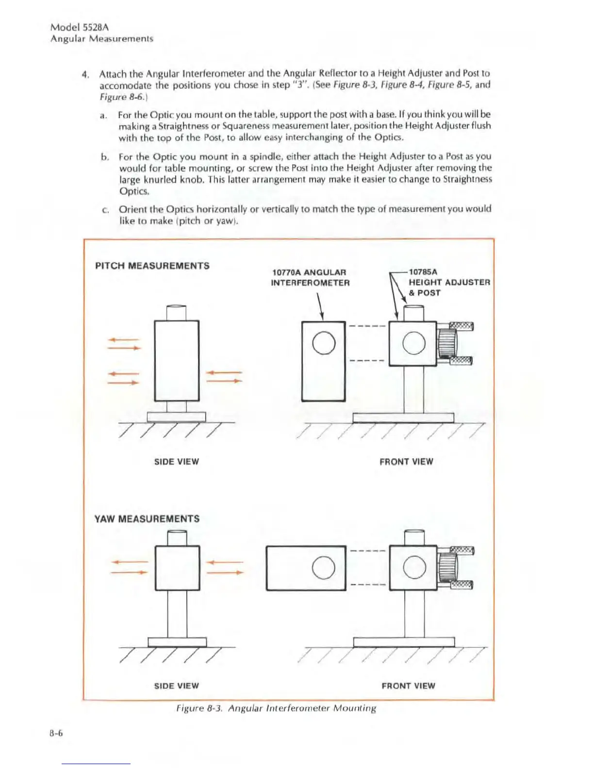
4. Atlach the Angular Interferometer and the Angular Re
fledor
to a Height Adjuster and
Post
to
accomodate the positions you
chose
in
step
"3".
(
See
Figure
8-3,
figur
e 8-4, Figure 8-5, and
Figure 8-6.)
a.
For
the Optic you mount on the table, support the post with a
base.
If you think
you
will
be
making a Straightness
or
Squarcnc5s
measu
rement later, posilion the Height AdJusterflush
with the
top
of
the
Post,
to allow
easy
interchanging
of
the Optics.
b.
For
the
Optic
you mount
in
a spindle, either attach Ihe Height
Ad
juster to a P
os
t
as
you
would for table mounting, or
sc
rew the
Po
st
in
to Ihe Height Adju
ste
r after removing the
large knu
rl
ed
knob.
Th
is latter arrangement
may
make it
ea
sier to change to Straightness
Opti
cs.
c.
Orient the
Opti
cs
horizontally or vertically to match the type of
mea
surement you would
like to make (pitch
or
yaw
).
PITCH MEASUREMENTS
•
•
•
•
•
•
S
ID
E
VI
EW
YAW
MEASUREMENTS
•
•
•
•
S
ID
E
VI
EW
10
77
0A ANGULAR
INTERFEROMETER
HEIG
HT
ADJU
STER
& POST
\
~L.........,
____
_ ,-ll-.....L...
t-
o o
-
--
- -
~---,-
t-
/
FRO
NT
VIEW
,-----,
_____
,.....-l---'-"""\-
o
o
'------'
-
----
L.....,.---,-...r-
/
/
FRONT
VI
EW
Figure 8-3. Angular
Inlerferomeler
Moufltin8