Model
5528A
Flalness Measurements
9·10
d.
Sw
itch back 10 the Iilrge exil
por
i aperlure and the f
ull
y
open
relurn
POri
.
e.
Check again for BEAM
ST
R
ENGT
H.
If
a
li
g
nm
ent
is
still n
ol
good
eno
ugh to make BEAM S
TRENGTH
read in ils gr
ee
n
area
,
repeat the e
ntir
e
Alignment
pro
ce
dur
e.
MEASUREMENT
DISPLAY
SETTINGS
Measurement
Units
The
di
splayed
unit
s for
yo
ur
Flatness meas
ur
ement
(s)
will be
id
enti
ca
l to th
ose
for
an
Angular
meas
ur
eme
r,1.
Rev
iew
"MEASUREMENT UN
IT
S"
information
In Section a of this User
's
Guide.
Measurement
Mode
Key
s
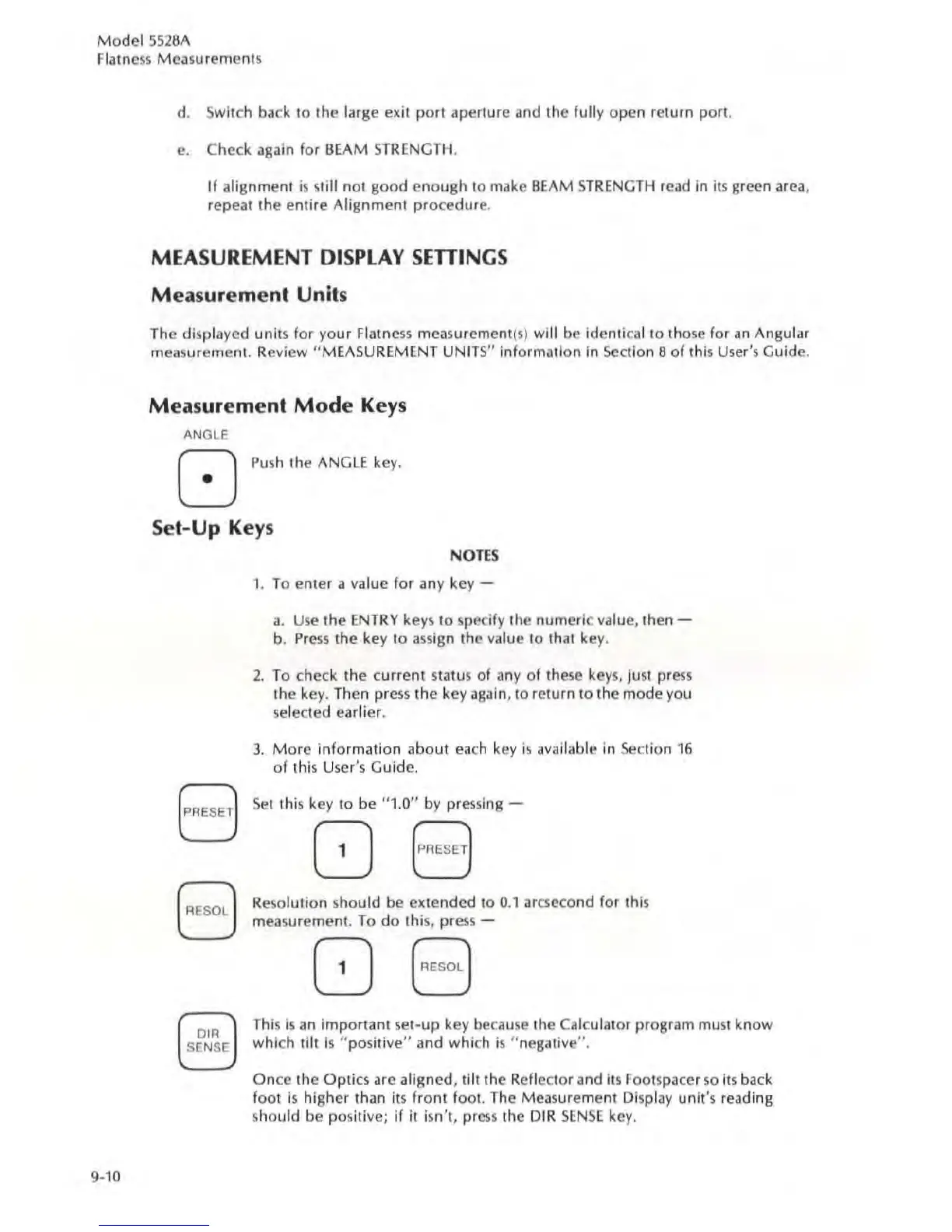
ANGLE
[]
Push
'h
e ANGLE ke
y.
Set-Up
Keys
t
AESE
J
[
AESO
j
Io;;;J
~
N
OTES
1. To enter a
va
lue for any key -
a.
Use
the
ENTRY
keys
to
specify the
num
er
ic
va
lu
e,
the
n-
b.
Pr
ess
the key to assign the
val
ue to that key.
2. To check the
curre
nt
status of
any
of
these keys, jusl press
the key.
Th
en press the
ke
y again, to return to the mode you
se
lected earlier.
3.
More
Information
about
eac
h key
is
available in
Sec
tion
16
of
this User's Guide.
Se
t this key to be "1.0" by
pr
essing-
08
Resolution sho
uld
be exte
nd
ed
to
0.1 arcseco
nd
for this
m
eas
ur
emen
t.
To
do
thi
s,
pres
s-
08
Th
is
is
an
imp
ortant
se
t-up key because the Calculator program muSI
know
which
tilt
is
" p
ositive"
a
nd
which is " nesative
".
On
ce the Optics are aligned,
lill
the Reflector and ils F
oo
tspacer
so
Its
ba
ck
f
oot
is
higher than its
front
foot. The Measurement Display unit's reading
sho
uld
be positive; if it isn't, press the
DrR
SENSE
k
ey.