MAKING A
MEASUREMENT
System Checks
1.
Milke
sure both laser Head
porls
<lfe
switched
10
their
large
apertu
r
e$.
2. The
laser
Head
turret must be set
10
"
Olher"
,
3. The
laser
Head's
READY
indic
ator
mu
st be
lishl
ed steadily (i.e.,
not
blinking
).
4.
Make
sure
your
Laser
Measurement System
is
properly
co
nnected
to
the
HP
Dimensional
Metrology
Analysis System.
Make sure
the
Measurement Display
15
set-up to accept a
co
ntroller
via
HP-18
. Follow
the
Instructions
for
"Data Transfer
with
an HP-IB
Contro
ll
er",
in Section
18
of
this User's G
uide
.
Procedure
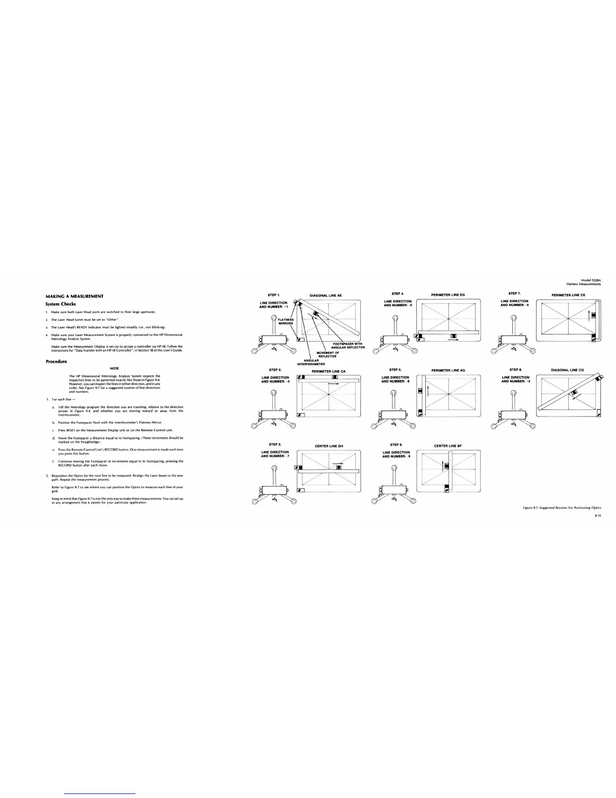
Non
The
HP
Dimensional
Melrology
Analysis System expects the
inspection lin
es
10 be patterned exactly like Ihose in Figure 9-4 ,
However, you can insped
Ih
e lines
in
either
direction
, and
in
any
order,
See
Figure 9-7 for a
SutUj:cs
led
rouline
of
lin
e directions
and numbers,
1. For cach linc -
a,
Tell the
Melrology
program
Ihe
direction
you arc traveling, relative
to
the
direction
arrows in
figure
9-4, and
whether
you are moving toward or
away
from
Ihe
I
nlerlerome
ler,
b. PasHion Ihe Footspa cer fl
ush
wilh
Ihe
Inlerferomeler's Flalness
Mirror
,
c,
Press
RESET
on the Measurement Display
unit
or
on
Ihe
Remote Control unit.
d,
Move
the Footspacer a distance equal to its footspacing./These increments s
hould
be
marked
on
the
St
rai
ghtedge.)
e,
Press
the Remote
Conlro
l Unit's RECORD bUll
on
,
One
measurement
is
made
ea
ch time
you
press
this
bullon
.
f, Co
ntinue
moving Ihe Foolspacer in
in
crements equa l
to
its footspacing . pressing
Ihe
RECORD bUllon afler each move,
2. Repos
ition
the Optics for
the
nexi line
to
be measured. Realign the laser beam to
Ihe
new
palh, Repeat
Ihe
measuremenl process,
Refer
to
figure
9-7
to
sec
where you c
an
position the Optics to measure each line
of
your
grid.
Keep
in
mind
Ihal Figure 9-7
is
not
Ihe
only way
to
make
Ih
ese
measuremenl
s.
You
can
set
up
In
any
arrangemenl th
ai
is
easiest
for
your parlicutar application.
STEP 1.
LINE
DIRECTION
AND
NUMBER
: + 1
<ff
FLA
THEIS
II
MIRRORS
,
STEP 2.
LINE
DIRECTION
AND
NUMBER: -3
STEP 3.
LINE
DIRECTION
AND
NUMBER
: - 7
•
DIAGONAL
LINE
I.E
FOOT'PACER
WITH
ANGULAR REFLECTOR
MOVEMENT OF
REFLECTOR
ANGULAR
INTERFEROMETER
PERIMETER LINE
CA
CENTER
LINE
DH
STEP
4.
LINE
DIRECTION
AND
NUMBER: - 5
STEP 5.
LINE
DIRECTION
AND
NUMBER:
-e
STEP
I.
LINE
DIRECTION
AND
NUMBER: -I
•
PERIMETER LINE EG
PERIMETER
LINE
loG
CENTER
LINE
BF
STEP 7.
LINE
DIRECTION
AND
NUMBER
:
-4
STEP I .
LINE
DIRECTION
AND NUMBER: +2
•
ModelSS28A
FIOiIIlness
MeasuremenlS
PERIMETER LINE
CE
DIAGONAL
LINE
CG
fiRure 9
-7.
Suggested Routine
For
Posili
on
ing
Opti
cs
9-
11