Mode
l 5528A
Straightn
ess
Measurements (Al
ong
A
Horizontal
Axis)
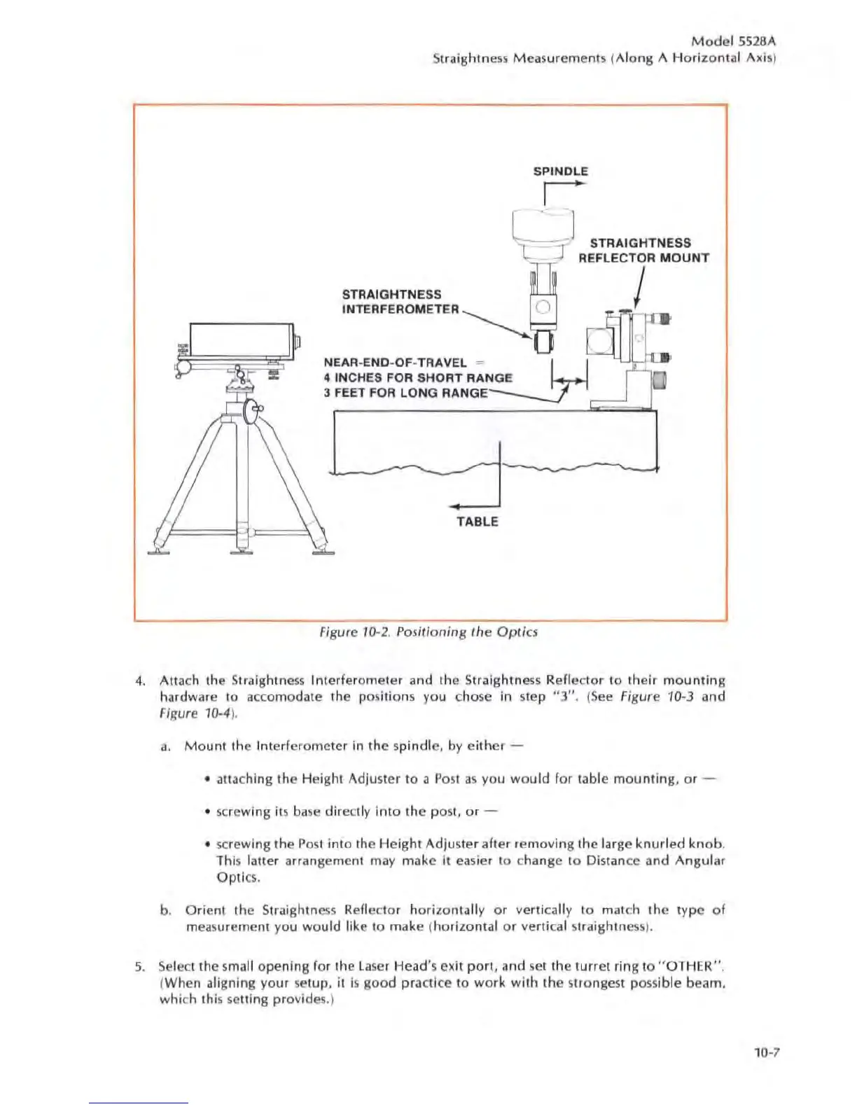
SPINDLE
r
C
'-
=--_,:::
J STRAIGHTNESS
- --J REFLECTOR MOUNT
STRAIGHTNESS
INTERFEROMETER
~
0
NEAR
-E
NO
-
OF
-TRAVEL
=
~
4 INCHES FOR SHORT RANGE
3
FEET
FOR
LONG RANGE
TABLE
Figure 10-2. Positi
oni
ng
'he
OpOcs
I
4. Auach the Straightness Interferometer and the Straightness Reflector
10
their
mounting
hardware to accomodate the positions you chose in step "3".
(See
Figure 10-3 and
Figure
10-4
).
a.
Mount
the Interferometer in the spindle, by
either
-
• anaching the Height Adjuster
to
a
Po
st
as
you
would
for table
mounting
,
or
-
• screwing
ilS
ba
se
direc
tl
y
into
the post.
or
-
•
sc
rewing the
Post
into
the
Height
Adjuster after
removing
the large
knurled
knob
.
This
latter arrangement may make it easier
to
change to Distance and
Angular
Optio.
b.
Orient
the Straightness Reflec
tor
hori
zontally
or
vertically
to
malch
the
type
of
mea
s
ur
ement you
would
like
to
make (
horizontal
or
verti
ca
l straightne
ss
).
5.
Select the
sma
ll
opening
for the
la
ser Head's exit
port.
and
set
the
turret
ring
to
"OT
HER".
(When aligning your
set
up
, it
is
good
practice
to
work
with
the
st
rongest possible beam.
which this setting provides
.)
10-7