Model
552
8A
Slraightness
Measuremen
ts (Along A Horizon
tal
Ax
is)
SPINDLE
OR
OTHER SUPPORT
I
1
o
"'"
I
,
I
,
,
I
,
~
'POSTFROM
10776A
ACCESSORY KIT
OR
10785A
HEIGHT
ADJUSTER
II.
POST
1078SA
o
~
HEIGHT ADJUSTER
,
I
I
,
I.
.,
'I
,!
~
BASE FROM 10778A
I I
' ,
, I ACCESSORY KIT
,
,
I
,
I
,
,
@
_____
10774A OR 10775A
r STRAIGHTNESS INTERFEROMETER
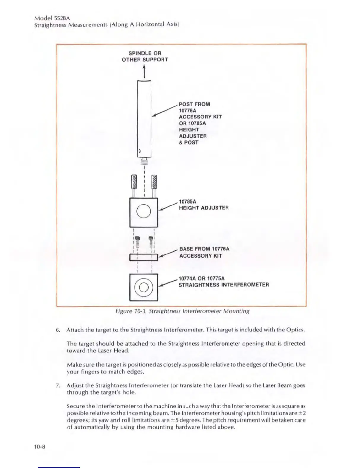
FIgure
10
-3
.
StroJ/gh/ness
I
llterferomeler
Mounting
6.
Atlach the ta
rg
et to
the
Straightness Interferometer.
Th
is
ta
rg
et is included whh
the
Op
t
ics
.
Th
e target should
be
attached
10 the Straightness Interferometer opening that is
dircded
toward the l aser Head.
Make sure the target is
po
sitioned 35 clo
se
ly
as
possible relative
to
the edges of the
Op
t
ic.
Use
you r fingers
to
match edges.
7.
Adjust
the
Slraightness Int
erferome
t
er
(o r translate
the
l aser Head) so the laser Beam goes
through
the target's hole.
Secure
the
Int
e
rf
erome
t
er
to
the mac
hine
in
such a
wa
y
th
ai
the
Int
erfer
ometer
is
as
squa
re
as
possible
relative
to
the
incoming beam.
Th
e Interferometer hous
in
g's pitch l
im
itations are ± 2
degrees
;
it
s yaw a
nd
rolilimilations are ± 5 degrees. The pitch
requ
irement
wi
ll
be taken care
of
automatica
ll
y by using
th
e
moun
ting hardware listed above.
 Loading...


