ModelSS28A
Straightness Measurements (
Along
A Hori
zo
ntal Axis)
Misalignment Between Machine Travel
and
the
Laser
Measurement
Axis
(Slope)
Description
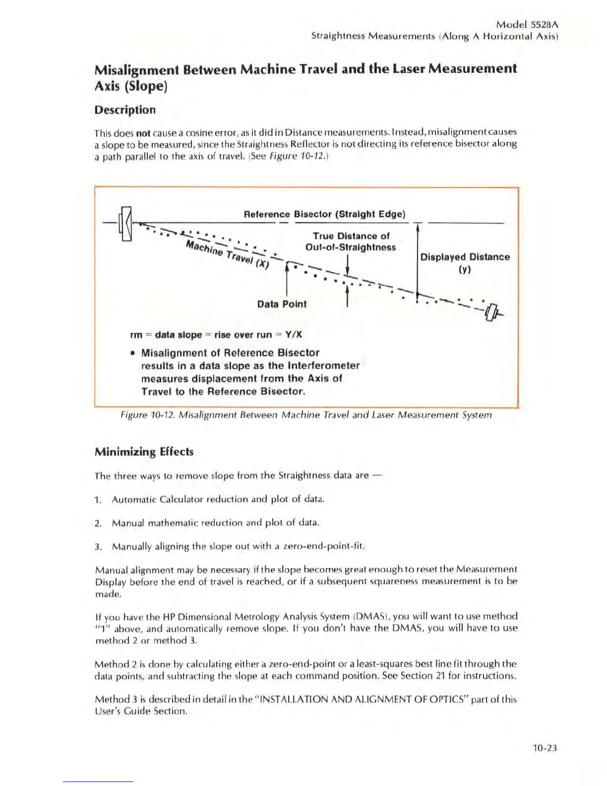
This does not c
au
se
a
cos
ine error,
as
it
did
in Distance measurement
s.
Instead, misalignment causes
a slope to be measured, since the
Straig
htne
ss
Refleoor
is
not
direc
ting Its reference
biseoor
al
ong
a path parallel
to
The
axis
of
travel.
(See
Figure 10-12.)
O
Reference Bisector (Straight Edge)
--
I-~·,,~----
------~~=
..
~
~
..
• - -..:.. • • True Distance of
4t
aC1
I/n";'
T":"':
~
• Out-of-Straightness
ro,./ (Xi -
r.
-:-
.-;
J:-.
-,..
>--
Data Point t
'.
-:-
rm
= data slope = rise over run
""
Y IX
• Misa
lignment
of
Re
ference
Bisector
results
in
a data slope as
the
Interferometer
measures
displacement
from
the
Axis
of
Travel
to
the
Reference
Bisector.
Displayed Distance
(y)
.
--
---
.
...:.!(}-.
Figure
10-12.
Misalignment Between
Machine
Travel
and
La
se
r Measurement System
Minimizing Effects
The thr
ee
ways
to remove slope from the
St
raightness data are -
1. Automatic Calculator reduction and pi
al
of
data.
2.
Manual mathematic reduction and pl
ot of
data.
3.
Manually aligning the slope out with a zero-end-point-fi!.
Manual alignment
may
be ne
cessa
ry
if the slope beco
mes
great
enough
to reset the Meas
urement
Display before the end
of
travel is reached, or
if
a
su
b
se
quent squareness measurement is to be
made.
If you have the
HP
Dimensional
Metrology
Analysis
System
(DMAS), you will want to u
se
method
"1"
above, and automatically remove slope.
If
yO
ll
don',
have the
DMA
S,
you wi
ll
have to use
method
2
or
method
3.
Method
2
is
done
by
calcu l
at
ing either a
zero-end-point
or
a least-squar
es
best line fit through the
data points, and subtra
ct
ing the slope al each comma
nd
position.
See
Section
21
for
instructions.
Me
thod 3 is described in detail in the "INSTALLATION
AND
ALIGNMENT OF OPTICS" part
of
this
User's Guide Section.
10-23