Model
5528A
Straightness Measurements (Along A Horizontal Axis)
10
~22
Laser
Sy
s
tem
Error Sources
Error sources
within
the
La
ser
Measurement
System
are -
it.
Straightness Reflector
mirror
s.
b.
Mis
~
3lignment
between
the
machine's travel
axis
and the laser Measurement
axis
("slope"
).
c.
Environment (e.g.,
ma
chine and atmosphere).
Straightness Reflector Mirrors
D
esc
ription
The
limiting accuracy
of
a Straightness
mea
surement is directly related to the accura
cy
of
the mirror
ca
libration factor and to the difference in flatness of the two plane mirrors that
serve
as
the
Slraightness Reflector. V.O.l. error
is
nesligible
co
mp<lred
to the overall measurement accuracy.
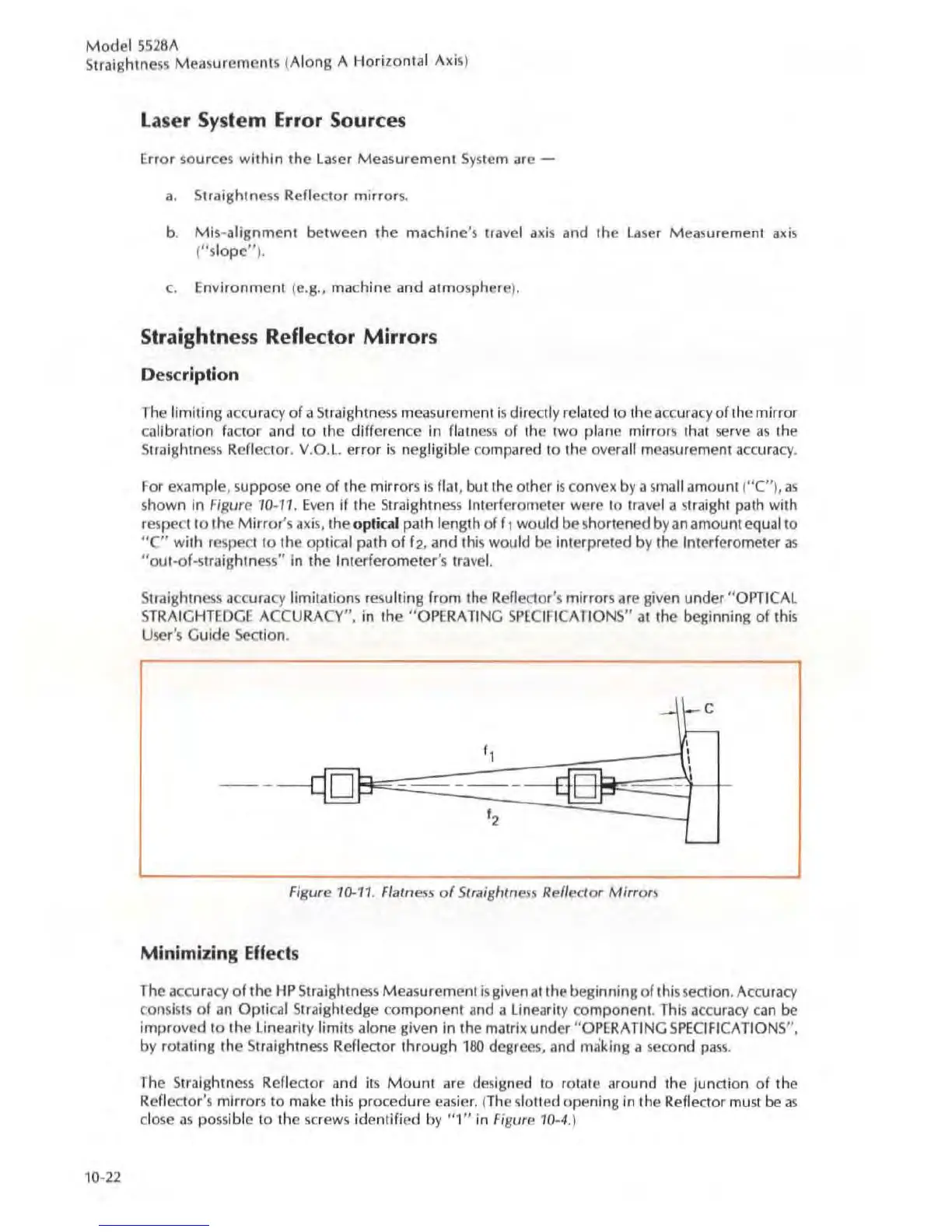
For
exa
mple, suppose one
of
the mirrors is flat, but the other is convex by a
sma
ll amount (
"C"
),
as
shown in Figure '
10-11
.
Even
if the Straightness Interferometer were to travel a straight path with
respect
to
the Mirror's
axis,
the o
pl
ic::a
l path length of r t would
be
shortened by
an
amount equal 10
"c" with respect
to
the optical path
of
f
2,
and this would
be
interpreted by the Interferometer
35
"ou
t~of~
straig
htn
ess"
in the Interferomctcr
's
tra
ve
l.
Slraightn
ess
accu
ra
cy
limitations resulting from the Reflector's mirrors are given under
"O
PTICAL
STRAIGHTEDGE
ACCURACY", in the
"O
PERATING
SPECIFICATIONS"
at
the beginning of this
User's Guide Section.
-
Figure
10-11
. Fialn
css
of
Slraighlness Rel/eclor
Mirrors
Minimizing
Eff
ec
ts
The
accuracy
of
the
HP
Straightness Measurement
is
given
at
the beginning
of
this section. Accuracy
consi
s1.S
of
an
Optical Straightedge component
and
a linearity component.
This
accuracy c
an
be
improved
to
the
lin
ea
rity limits alone given in the mauix under
"OPE
RATING S
PECIFICATIONS
" ,
by rotating the Straightness Reflector through
180
degrees, and making a
seco
nd
pa
ss.
The Straightness Reflector and its
Mount
are
designed to rolate around the junction
of
the
Reflector's mirrors
to
make this procedure easier. (
The
slolled opening
in
the Reflector
must
be
as
dose
as
possible
to
the screws identified
by
"1"
in
Figure
10~4
.
)