Model
5528A
Straightness
Mea
s
urement
s
11
-20
4. Reset the Measurement Display, and return the machine to the near end
of
travel.
5. At the near end
of
travel, move the Interferometer
or
the Reflector in a direction
parallel
with
the slotted opening
in the Reflector until the Measurement Display
reads
zero.
If
beam strength again gets too
low
,
turn
the
Laser
Head 10 regain adequate beam strength, and
trans
lat
e the
Laser
Head to prevent
clipping
of the beam by Ihe Interferometer.
6. Repeat step
" 1" through step " 5"
as
often as
ne
c
es
s
ary
to make measurementS
at
both ends
of
travel
come
out
to
be " zero" .
Other
Mounting
Requirements
Although
we have
tried
to
provide
you
with
a maximum
of
mounting
flexibility, there may be
situations
when
you need
more
capability. For
more
information
, you s
hould
turn
to Appendix C
for
dimension
s
of
the
Opti
cs and the
mounting
hardware.
MEASUREMENT
DISPLAY
SETTINGS
NOT
E
Measurement Display settings
are
the same
with
or
without
sensors.
Measurement
Mode
Keys
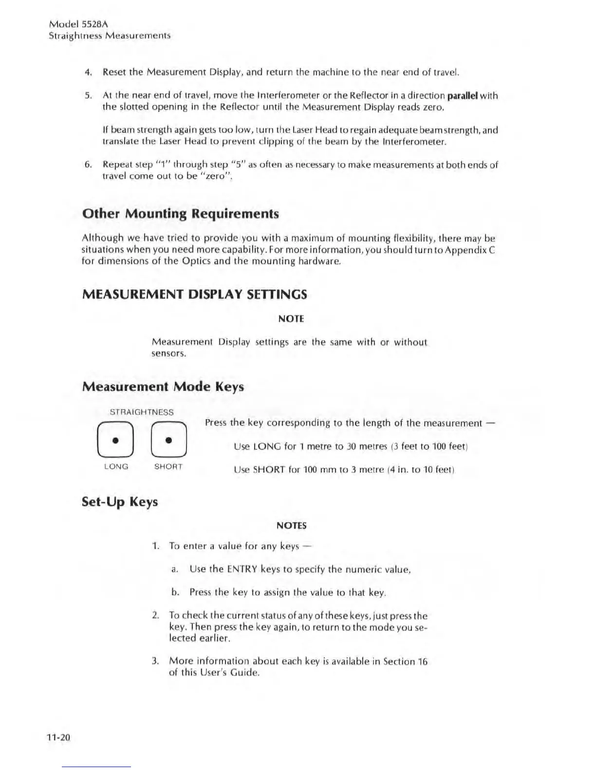
STRAIGHTNESS
00
Press
the key corresponding to the length
of
the measurement -
Use
LONG
for
1 metre to
30
metres (3 feet to
100
feet)
LO
NG SHORT
Use
SHORT for
100
nun to 3 metre (4 in. to
10
fee
t)
Set-Up
Keys
NOTES
1.
To
enter
a
va
l
ue
for
any key
s-
a.
Use
the
ENTRY
keys to specify the
numeric
va
lue,
b.
Press
Ihe
key
10
assign the value to that key.
2.
To
check the cu
rr
ent status
of
any
of
these keys,
Just
press the
key. Then press the key again, to return
to
the
mode
you
se
-
lected earlier.
3.
More
information
about
ea
ch key is available in
Sec
tion
16
of
this User's
Guide
.