Model
5526A
Squ3reness
Measurement
s (In A
Hori
zontal Plane)
1
2-
12
y
l(z
X
STRAIGHTNESS REFLECTOR
S
TRAI
GHTNE
SS
INT
ERFEROMET
ER
STRAIGHTNESS
RETAOREFLECTOR
.,.--O
PTICAL
SQUARE
~
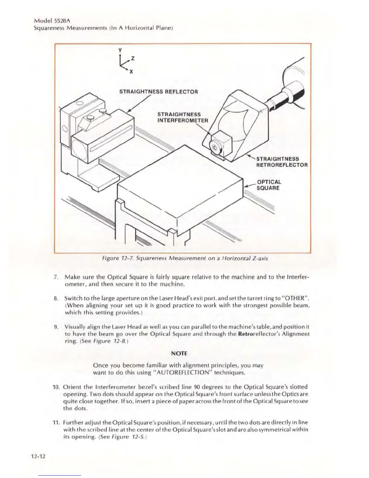
Figure
12
-7. Squarelless Measuremeflf on a Horizon/al Z-axis
7.
Make
sure the
Opti
ca
l Square
is
fairly square relative to the
ma
c
hine
and
to
the Interfer-
omete
r, and then secure it to the
ma
c
hine
.
8. Switch
to
the
large aperture on the
la
se
r Head's
ex
it port, and
se
t the turret ring to "
OT
H
ER
".
(
Whc
r, al
igning
your
s
et
up
it
is
good
practi
ce
to
work
with
the strongest possible beam,
which
thi
s
se
tting
provide
s.)
9.
VisuaJJy
align the
laser
Head
as
we
ll
as
you c
an
parallel to the
ma
c
hine
's
table, and
po
sition
it
to
ha
ve the beam go over the
Optical
Square and
thr
o
ugh
the Re
lr
oreflc
ctor's Alignment
ring.
(See Figure 12-8.)
NOTE
Once
you become familiar
with
alignment
prin
cipl
es,
you may
want
to
do
this using " AUTOREFlE
CT
ION
" tec
hniqu
es
.
10
.
Orient
the Interferometer bezel's sc
ribed
line
90
de8rees to the
Opti
ca
l Square's slotted
opening
.
Two
dots s
hould
appear
on
the Optical Square's front surface
unl
ess
the Optics are
quite
clo
se
together
. If so. ioser! a piece
of
paper across the front
of
the Optical Square to
see
the dot
s.
11
.
Further
adjust the
Optical
Sq
uare
's
po
s
ition
, if n
ecessa
ry
, until the
two
dot
s are
dire
ctly in line
with
the scribed
line
at
the cent
er
of
t
he
Optical Square's s
lot
and are also symmetrical
within
its
opening.
(
See
Figure 12-5.)