Model
5528A
Squltreness
Mea
s
uremenls
(In A
Horizontal
Plane)
STRAIGHTNE
SS
RETROREFLECTOR
__
~
_I
-=:::~
c---
i
--
ALIGNMENT
\ RING
y
INT
E
RF
ERO
MET
ER
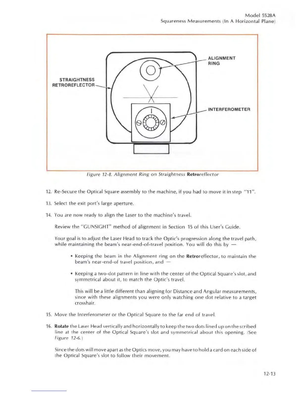
Figure 1
2-8.
Alignmenr Ring
on
Srraightness Re
tr
orefle
c
lor
1
2.
Rc
-5
ecure the Optical Square assembly 10 the machine, if you had to move it in step "
11
".
13
.
Se
leci
Ihe
ex
it pori's I,ugc aperture.
14
. You are
now
ready to align the
la
ser to the
ma
ch
ine'
s travel.
Review the
"CUNS
I
GHT"
method
of
alignment in Section
15
of
this
Use
r
's
GUide.
Your goal is
10
adju
st
the
la
se
r Head
to
track the
Opti
c's progression along the travel path,
while
maintaining the beam
's
near-e
nd
-of-travel posit
ion
. You
wi
ll
do
thi
s by -
• Keeping the beam in the
Alignment
ring
on
the
Re
tr
oreflc
c
tor
, to maintain the
beam's ncar-end
-o
f travel
position,
and -
• Keeping a tw
o-
dol
pallern
in
lin
e
with
the center
of
the
Optical
Square'!'. sial,
and
sy
mmetrical about it, to match the
Optic's
travel.
This
will
be a
liule
different than aligning
for
Distance and Angular measurements,
since with Ihe
se
alignments you were
only
watching
one
dOl
relative to a target
cro
ss
hair.
15
.
Mo
ve
the
Inlcrferomele
r or the Optical Square to the far end
of
tra
ve
l.
16
. Rolale the
la
ser
HCild
ve
rt
ica
lly and
hori
zo
ntally to keep the
two
dot
s l
ined
up
on
Ihe
sc
rib
ed
line
al
the center
of
lhe
Optical Square's 5101 and
sy
mme
lr
ic
al
about
this o
pening
. (
See
Figure 12-6.)
Since the dots will move aparl
as
the Optics move, you
ma
y have to
hold
a
ca
rd
on
each s
ide
of
the Optical Square
's
slot to follow th
eir
movement
.
1
2-
13