Model 5528A
Measurements
Using a Plane
Mi
rror Int erf
ero
m
eter
Alignment Aids
To help
in
aligning the pl
ane
mi
rr
or interferometer, two alignme
nt
aids are includ
ed.
They are:
• A
li
gnme
nt
Target (PIN 10702-
600(
1)
(
See
figure D-
4)
•
Alig
nme
nt
Aid
(P
IN
10706-60001) (See Figure
0·4)
!loth alignment aids are
ma
gnetic
to
simplify positioning th
em
on
the interferometer.
The
alignment tar
ge
t is used on the input
si
de of
the
interf~rometer
to
propedy position
the
beam In
the
Input aperture.
The
alignment aid
is
pla
ced
on the
exit
ape
rture (on
the
plane mirror conve
rt
er) to a
ll
ow
using
the
autoreficcUon method of a
li
gning
the
plane mirror interferom
ete
r. The alignment aid
needs
to be propcdy oriented so that the primary
mea
s
urement
beam
goes through the hole
on
the
alignment ald. The primary measurement
beam
is
the
first
of two
measurement
beam
s that go
between the Interferometer and the
pl
ane
mirror. To find the primary beam, block
one
of
th
e
t
wo
measurement
beam
s
and
if
th
e other disappears, th
en
th
e
one
blocked
Is
the
pri
mary
measur
ement beam.
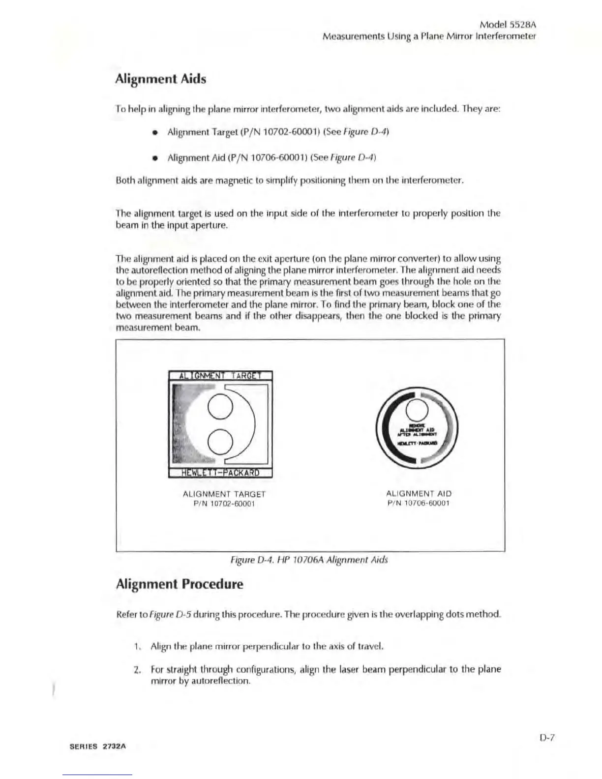
ALIGNMENT TARGET
PIN 10702·60001
ALIGNMENT AIO
PIN 10706·60001
Fi
gu
re 0-4.
I-IP
10
706A
Alignment
Aids
Alignment Procedure
Refer to
Figure
0 -5 during th
is
procedure. The
procedure
given is the ovedapping
dot
s method.
SE
RIES 2732A
1.
Al
ig
n
the
plane mirror perpendi
cu
lar
to
the axis
of
travel.
2.
For
straight through
co
nfi
gura
ti
ons, align
the
l
aser
beam
perpendicular
to
the
plane
mirror
by
aUlorefiection.
D·l