41
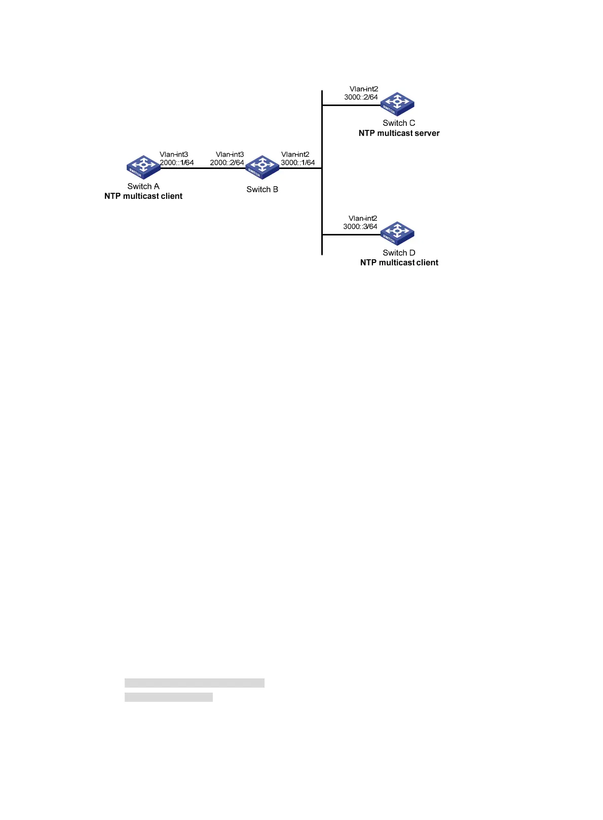
Figure 15 Network diagram
Configuration procedure
1. Set the IP address for each interface as shown in Figure 15. (Details not shown.)
2. Configure Switch C:
# Enable the NTP service.
<SwitchC> system-view
[SwitchC] ntp-service enable
# Specify the local clock as the reference source, with the stratum level 2.
[SwitchC] ntp-service refclock-master 2
# Configure Switch C to operate in IPv6 multicast server mode and send multicast messages
through VLAN-interface 2.
[SwitchC] interface vlan-interface 2
[SwitchC-Vlan-interface2] ntp-service ipv6 multicast-server ff24::1
3. Configure Switch D:
# Enable the NTP service.
<SwitchD> system-view
[SwitchD] ntp-service enable
# Configure Switch D to operate in IPv6 multicast client mode and receive multicast messages on
VLAN-interface 2.
[SwitchD] interface vlan-interface 2
[SwitchD-Vlan-interface2] ntp-service ipv6 multicast-client ff24::1
4. Verify the configuration:
# Because Switch D and Switch C are on the same subnet, Switch D can receive the IPv6 multicast
messages from Switch C without being enabled with the IPv6 multicast functions and can be
synchronized to Switch C. Display the NTP status of Switch D after clock synchronization.
[SwitchD-Vlan-interface2] display ntp-service status
Clock status: synchronized
Clock stratum: 3
System peer: 3000::2
Local mode: bclient
Reference clock ID: 165.84.121.65

 Loading...