50
• Configure CE 1's local clock as a reference source, with the stratum level 2.
• Configure CE 1 to operate in symmetric active mode.
• Specify VPN 1 as the target VPN.
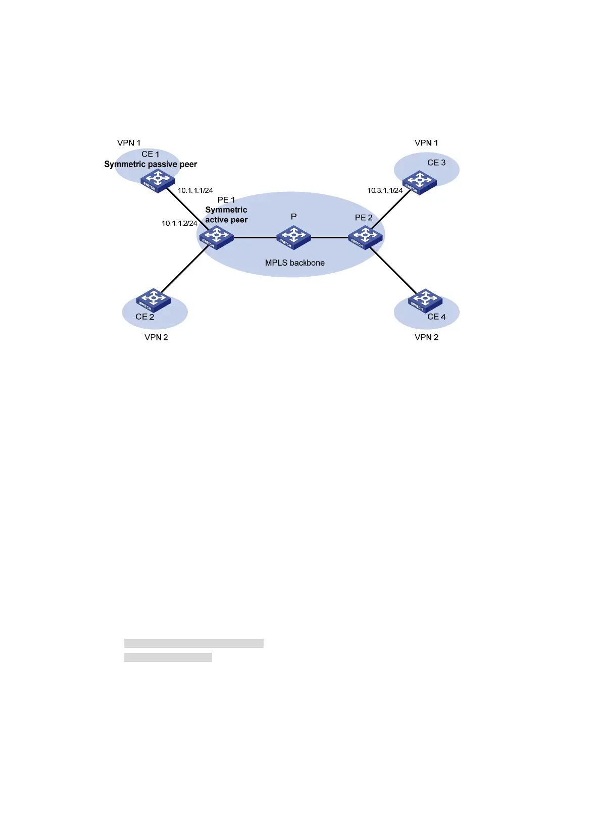
Figure 19 Network diagram
Configuration procedure
1. Set the IP address for each interface as shown in Figure 19. (Details not shown.)
2. Configure CE 1:
# Enable the NTP service.
<CE1> system-view
[CE1] ntp-service enable
# Specify the local clock as the reference source, with the stratum level 2.
[CE1] ntp-service refclock-master 2
3. Configure PE 1:
# Enable the NTP service.
<PE1> system-view
[PE1] ntp-service enable
# Specify CE 1 in VPN 1 as the symmetric-passive peer of PE 1.
[PE1] ntp-service unicast-peer 10.1.1.1 vpn-instance vpn1
4. Verify the configuration:
# Display the IPv4 NTP association information and status on PE 1 a certain period of time later.
[PE1] display ntp-service status
Clock status: synchronized
Clock stratum: 3
System peer: 10.1.1.1
Local mode: sym_active
Reference clock ID: 10.1.1.1
Leap indicator: 00
Clock jitter: 0.005096 s
Stability: 0.000 pps

 Loading...