Operation Model
8901B
The following table lists the different measurement range limits that can be selected with Special
bction
2
'
MODULATION
OUTPUT
Sensitivity
(Vac/% Hz)
Detector
Selected
Modulation
Range
(Peak2 kHz dev.)
Special
Function
Code
2.0 SPCL
2.4 SPCL'
Automatic Selection
10.04
Program Display
Code Resolution
(Hz)
2.0SP
Automatic
2.4SP 0.01
10.4
2.4 SPCL
2.4 SPCL'
2.1 SPCL'
14
2.4SP
2.4SP
2.1 SP
140
2.4 SPCL
2.1 SPCL
2.2 SPCL'
2.2 SPCL
2.3 SPCL'
2.3 SPCL
1400
2.4SP
2.1 SP 1
2.2SP
2.2SP
2.3SP
2.3SP
10
100
RMS
Pk,
Avg
Pk,
Avg,
RMS
Pk,
Avg
Pk,
Avg,
RMS
Pk,
AVQ,
RMS
Pk,
Avg,
RMS
Pk,
Avg,
RMS
I
I
0.1
i
e
I
e
ct
i
o
n
100
10
1
0.1
0.01
_____
'
With
750
ps
de-emphasis, pre-display only.
To
filter
the demodulated signal, press the appropriate
filter
keys. (Refer
to
Audio
Filters,
on page
3-179
for more information about
filters.)
If
de-emphasis equalization
is
desired, select the appropriate time
constant and display placement. (Refer
to
FM De-emphasis
on page
3-159
for more information about
filters.)
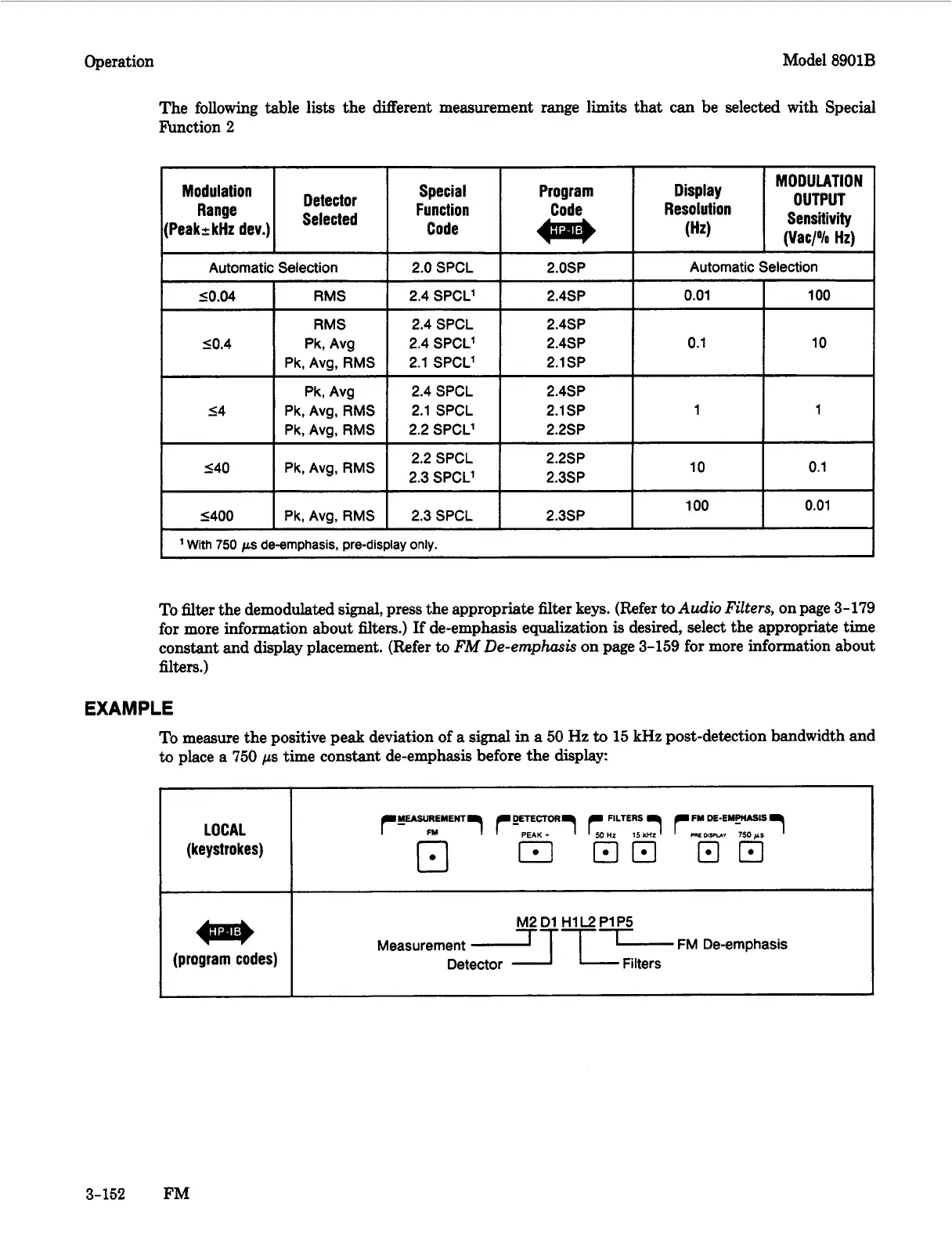
EXAMPLE
To measure the positive peak deviation
of
a signal
in
a
50
Hz
to
15
kHz post-detection bandwidth and
to
place a
750
ps
time constant de-emphasis before the display:
LOCAL
(keystrokes)
(program codes)
M2D1 HlL2PlP5
Measurement
LT--l
FM
De-emphasis
Detector Filters
3-152
FM

 Loading...


