Model
8901B
Operation
HP-IB
PROGRAM CODES
All HP-IB codes for setting range limits for FM measurements are provided
in
“Procedures”.
FM
=
M2
SPCL
=
SP
MEASUREMENT TECHNIQUE
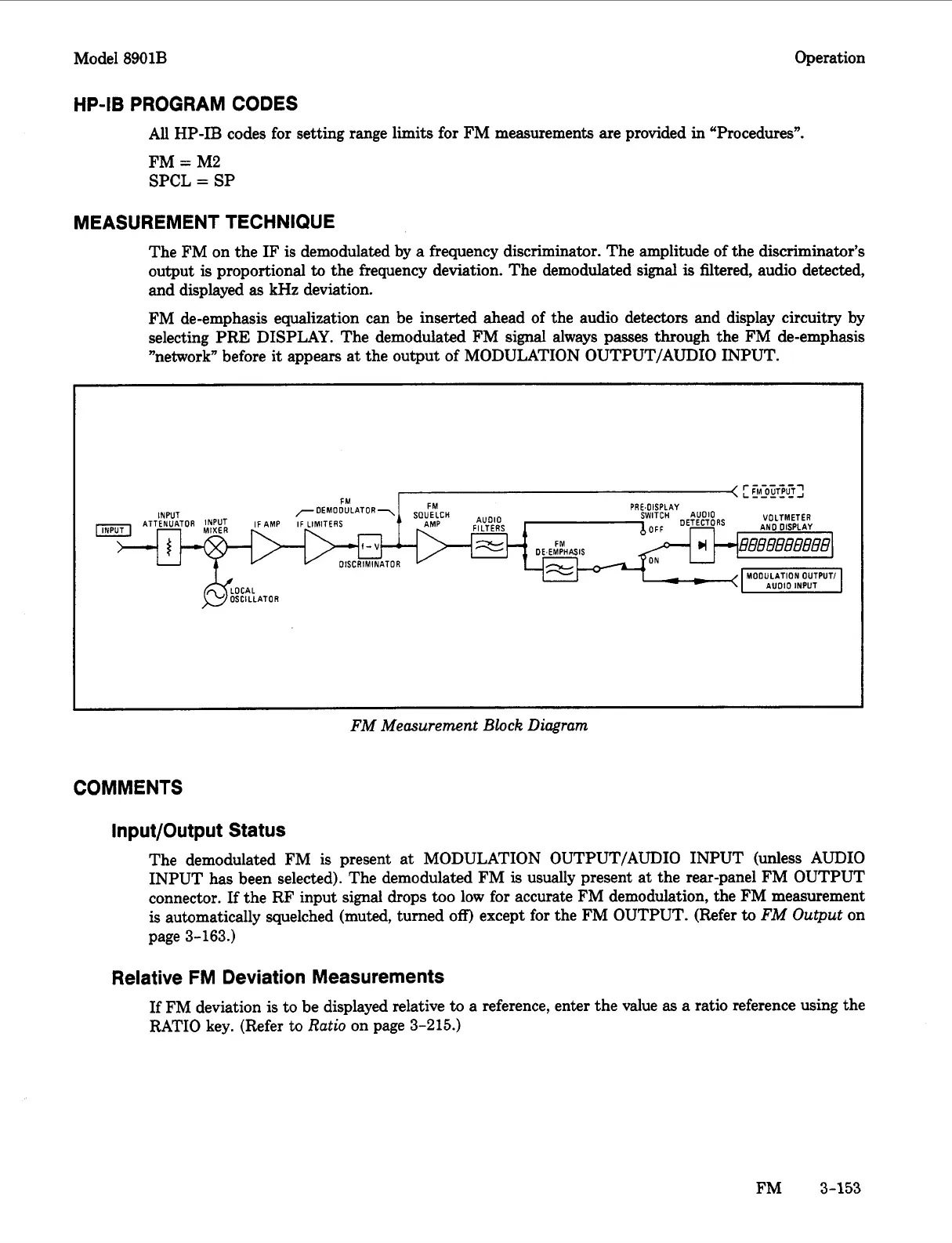
The FM on the
IF
is
demodulated by
a
frequency discriminator. The amplitude of the discriminator’s
output
is
proportional
to
the frequency deviation. The demodulated signal
is
filtered, audio detected,
and displayed
as
kHz deviation.
FM de-emphasis equalization can be inserted ahead of the audio detectors and display circuitry by
selecting PRE DISPLAY. The demodulated FM signal always passes through the FM de-emphasis
”network” before it appears at the output of MODULATION OUTPUT/AUDIO INPUT.
FM Measurement
Block
Diagram
COMMENTS
Input/Output Status
The demodulated FM
is
present at MODULATION OUTPUT/AUDIO INPUT (unless AUDIO
INPUT
has
been selected). The demodulated FM
is
usually present at the rear-panel FM OUTPUT
connector. If the RF input signal drops too low
for
accurate FM demodulation, the FM measurement
is
automatically squelched (muted, turned
off)
except for the FM OUTPUT. (Refer
to
FM Output
on
page
3-163.)
Relative FM Deviation Measurements
If
FM deviation is to be displayed relative
to
a reference, enter the value
as
a
ratio reference using the
RATIO key. (Refer
to
Ratio
on page
3-215.)
FM
3-153

 Loading...


