Performance Tests Model
8901B
Performance
Test
1
AM
TESTS
Specification
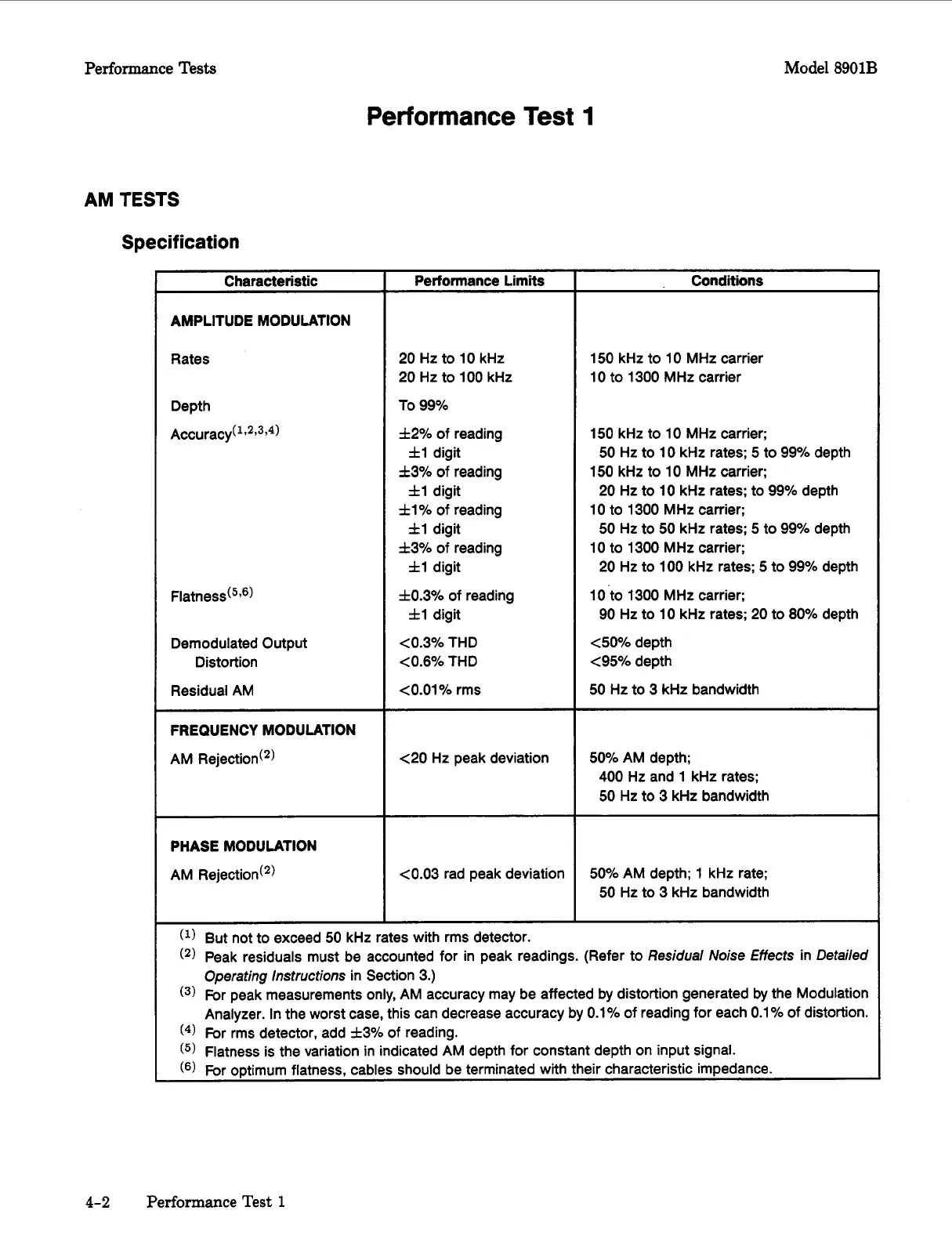
Characteristic
AMPLITUDE MODULATION
Rates
Demodulated Output
Distortion
Residual AM
FREQUENCY MODULATION
AM Rejection(2)
PHASE MODULATION
AM Rejectiod2)
Performance Limits
20
Hz to
10
kHz
20 Hz to
100
kHz
To
99%
f2%
of reading
f3%
of
reading
fl%
of
reading
f3%
of
reading
f0.3%
of reading
fl
digit
fl
digit
fl
digit
fl
digit
fl
digit
~0.6%
THD
~0.01%
rms
<0.3%
THD
c20
Hz peak deviation
~0.03
rad peak deviation
Conditions
150
kHz to
10
MHz carrier
10
to
1300
MHz carrier
150
kHz to
10
MHz carrier;
150
kHz to
10
MHz
carrier;
10
to
1300
MHz carrier;
10
to
1300
MHz carrier;
1O-to
1300
MHz carrier;
c50%
depth
~95%
depth
50
Hz to
3
kHz bandwidth
50
Hz to
10
kHz rates;
5
to 99% depth
20
Hz to
10
kHz rates; to 99% depth
50
Hz to
50
kHz rates;
5
to
99%
depth
20
Hz to
100
kHz rates;
5
to
99%
depth
90 Hz to
10
kHz rates; 20 to
80%
depth
50%
AM depth;
400
Hz and
1
kHz rates;
50
Hz to
3
kHz bandwidth
50%
AM depth;
1
kHz rate;
50
Hz to
3
kHz bandwidth
(l)
But not to exceed
50
kHz rates with rms detector.
(2)
Peak residuals must be accounted for in peak readings. (Refer to
Residual
Noise Effects in Detailed
Operating
instructions
in Section
3.)
(3)
For peak measurements only, AM accuracy may be affected by distortion generated by the Modulation
Analyzer. In the worst case, this can decrease accuracy by
0.1%
of
reading for each
0.1%
of distortion.
(4)
For rms detector, add
f3%
of reading.
(5)
Flatness is the variation in indicated AM depth for constant depth on input signal.
For optimum flatness, cables should be terminated with their characteristic impedance.
4-2
Performance Test
1

 Loading...


