118
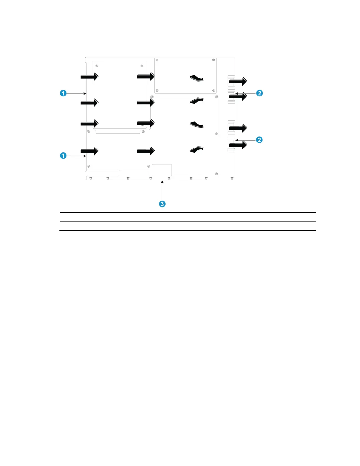
Figure 100 Airflow through the chassis
(1) Left-side inlet air vents
(2) Right-side outlet air vents
A5800-24G-PoE+/A5800-24G-PoE+TAA
Figure 101 shows the airflow design for the A5800-24G-PoE+ and A5800-24G-PoE+TAA switches. Cool
air flows in from the left side of the chassis, circulates through the chassis and the interface card, and
exhausts out the right side of the chassis.
 Loading...


