EasyManuals Logo

HP DL360 Maintenance And Service Guide

HP DL360
75 pages
To Next Page IconTo Next Page
To Previous Page IconTo Previous Page
Page #40 background imageLoading...
Page #40 background image
Removal and Replacement Procedures
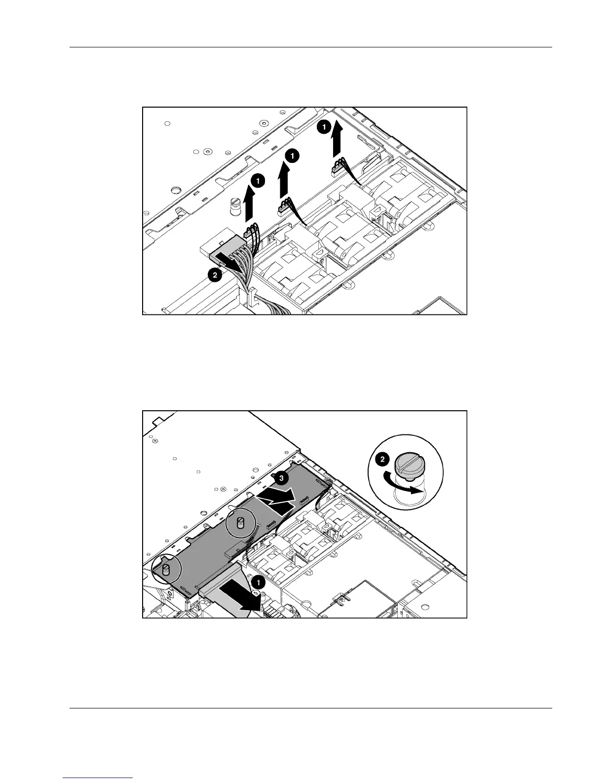
5. Disconnect the I/O system fan assembly power cables (1) and the optical device/diskette
drive interface board power cable (2).
Figure 2-32: Disconnecting I/O system fan assembly and power
converter module power cables
6. Disconnect the optical device/diskette drive cable (1).
7. Loosen the thumbscrews securing the interface board to the server chassis (2).
8. Pull the interface board forward, tip it, and remove it from the server chassis (3).
Figure 2-33: Removing the optical device/diskette drive interface
board from the chassis
Reverse steps 1 through 8 to replace the optical device/diskette interface board.
HP ProLiant DL360 Generation 3 Server Maintenance and Service Guide 2-29

Table of Contents

Other manuals for HP DL360

Questions and Answers:

Question and Answer IconNeed help?

Do you have a question about the HP DL360 and is the answer not in the manual?

HP DL360 Specifications

General IconGeneral
Processor Sockets2
CPUIntel Xeon Scalable
MemoryUp to 3TB DDR4
Form Factor1U Rack
Power SupplyRedundant Power Supplies, various wattage options
Network ControllerEmbedded 1Gb or 10Gb Ethernet
RAID SupportSmart Array RAID
Operating System SupportWindows Server, Linux, VMware
StorageUp to 10 SFF SAS/SATA/NVMe drives or 4 LFF SAS/SATA drives

Related product manuals