Do you have a question about the HP ProLiant DL360 and is the answer not in the manual?
Explains the meaning of various symbols used within the document text to convey specific information.
Provides crucial safety warnings and guidelines to be followed before installing or servicing the equipment.
Offers specific guidance and warnings for authorized Compaq technicians regarding repair procedures.
Lists additional resources and documentation available for users seeking further assistance or information.
Provides contact numbers for Compaq authorized resellers and technical support.
Defines the typographical conventions used in the document for emphasis, commands, and references.
Presents a visual breakdown of the server's mechanical components with numbered references.
Lists the part numbers for various mechanical components of the server for replacement.
Provides an exploded view illustrating the server's internal system components.
Details the part numbers for system components, facilitating identification for replacement.
Offers essential precautions and techniques to prevent damage from static electricity during handling.
Highlights critical warnings related to hot surfaces, electric shock, and proper system operation.
Outlines necessary steps to prepare the server before removing or replacing components.
Details the procedure for safely powering down the server to remove all electrical power.
Describes the types of mass storage devices supported by the ProLiant DL360 server.
Explains how to assess and remove hot-plug SCSI hard drives, emphasizing LED status.
Provides step-by-step instructions for removing and replacing the server's main access panel.
Details the procedure for removing and replacing the server's PCI riser board assembly.
Guides the user through the process of removing an expansion board from a 32-bit PCI slot.
Provides instructions for removing and replacing the server's power supply unit.
Offers guidelines and information regarding the installation and compatibility of system memory (DIMMs).
Details the procedure for removing and replacing the server's processor(s) and heatsinks.
Explains how to replace the system's real-time clock battery and associated precautions.
Outlines the comprehensive procedure for removing and replacing the main system board.
Illustrates the correct cable routing for the CD-ROM/diskette drive assembly backplane.
Shows the proper cable routing for the optional Smart Array/SCSI controller interface.
Depicts the correct cable routing for the Remote Insight Lights-Out Edition.
Introduces the software and firmware diagnostic tools available for Compaq server products.
Explains the initial default hardware and software configuration settings for the system.
Describes how to access the various Compaq utilities available on the system.
Details the automatic diagnostic tests performed by the system when it is turned on.
Explains the diagnostics software, its options, and how to interpret error codes.
Lists diagnostic error codes related to processor and system board failures.
Details diagnostic error codes associated with failures in the server's memory subsystem.
Describes the Array Diagnostic Utility (ADU) for diagnosing Compaq array controller problems.
Explains the Integrated Management Log (IML) for recording system events and errors.
Details the Automatic Server Recovery-2 (ASR-2) feature for automated system recovery.
Introduces Compaq Insight Manager for network device management, monitoring, and alerting.
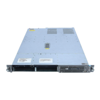
Provides an overview of the various connectors found on the server's rear panel and system board.
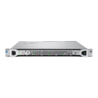
Illustrates and identifies the connectors located on the rear panel of the ProLiant DL360 server.
Shows the locations of key components and connectors on the server's system board.
Describes the system board switches used for server configuration and maintenance.
Explains the function and usage of the Non-Maskable Interrupt (NMI) switch for system analysis.
Provides an introduction to the status LED indicators on various server components.
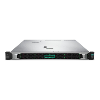
Identifies and describes the status LEDs located on the front panel of the server.
Details the status LEDs on hot-plug SCSI hard drives and their meanings.
Presents the physical dimensions, weight, and environmental specifications for the server unit.
Details the electrical and environmental specifications for the server's power supply.
Lists the specifications for SDRAM DIMM modules, including size, speed, and compatibility.
Provides specifications for the CD-ROM and diskette drive assemblies.
Details the specifications for the low-profile IDE CD-ROM drive, including performance metrics.
Lists the specifications for Wide Ultra2 SCSI hot-plug hard drives across different capacities.
Presents the specifications for the Integrated Smart Array Controller.
Provides specifications for the NC3163 embedded Fast Ethernet NIC controller with Wake-On-LAN.
| Max Processors | 2 |
|---|---|
| Form Factor | 1U Rack |
| CPU | Intel Xeon Scalable Processors |
| Storage | SAS/SATA HDD/SSD |
| Drive Bays | 8 SFF or 4 LFF |
| Network | 4 x 1GbE |
| Remote Management | Integrated Lights-Out (iLO) |
| Power Supply | Redundant Power Supplies |