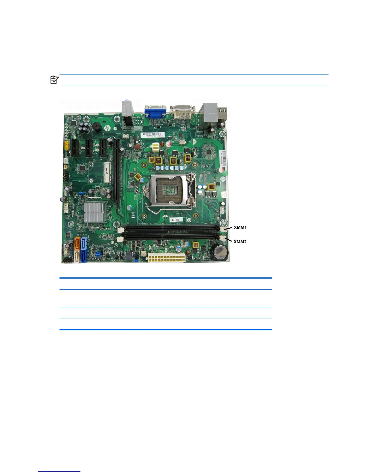
Populating DIMM Sockets
There are two DIMM sockets on the system board, with one socket per channel.
Populate the DIMM sockets in the following order: DIMM1, DIMM2
NOTE: System board appearance may vary.
Figure 8-5 DIMM Socket Locations
Table 8-1 DIMM Socket Locations
Item Description Socket Color Insertion Order
1 XMM1 socket, Channel A
(populate first)
Black 1
2 XMM2 socket, Channel A Black 2
NOTE: A DIMM must occupy the DIMM1 socket.
●
The system will operate in single channel mode if the DIMM sockets are populated in one
channel only.
●
The system will operate in a higher-performing dual channel mode if the total memory capacity
of the DIMM in Channel A is equal to the total memory capacity of the DIMM in Channel B. The
technology and device width can vary between the channels. For example, if Channel A is
populated with one 2-GB DIMMs and Channel B is populated with one 2-GB DIMM, the system
will operate in dual channel mode.
●
The system will operate in flex mode if the total memory capacity of the DIMM in Channel A is
not equal to the total memory capacity of the DIMM in Channel B. In flex mode, the channel
populated with the least amount of memory describes the total amount of memory assigned to
106 Chapter 8 Removal and Replacement Procedures Small Form Factor (SFF) Chassis

 Loading...