EasyManuals Logo

HP Elite 7500 Microtower User Manual

HP Elite 7500 Microtower
230 pages
To Next Page IconTo Next Page
To Previous Page IconTo Previous Page
Page #136 background imageLoading...
Page #136 background image
Front USB Assembly
Description Spare part number
Front I/O and card reader (6-in-1) 656983-001
The front USB assembly is secured to the front of the chassis with one screw. Push the assembly into
the chassis to remove it.
1. Prepare the computer for disassembly (
Preparation for Disassembly on page 101).
2. Remove the access panel (
Access Panel on page 102).
3. Remove the front bezel (
Front Bezel on page 104).
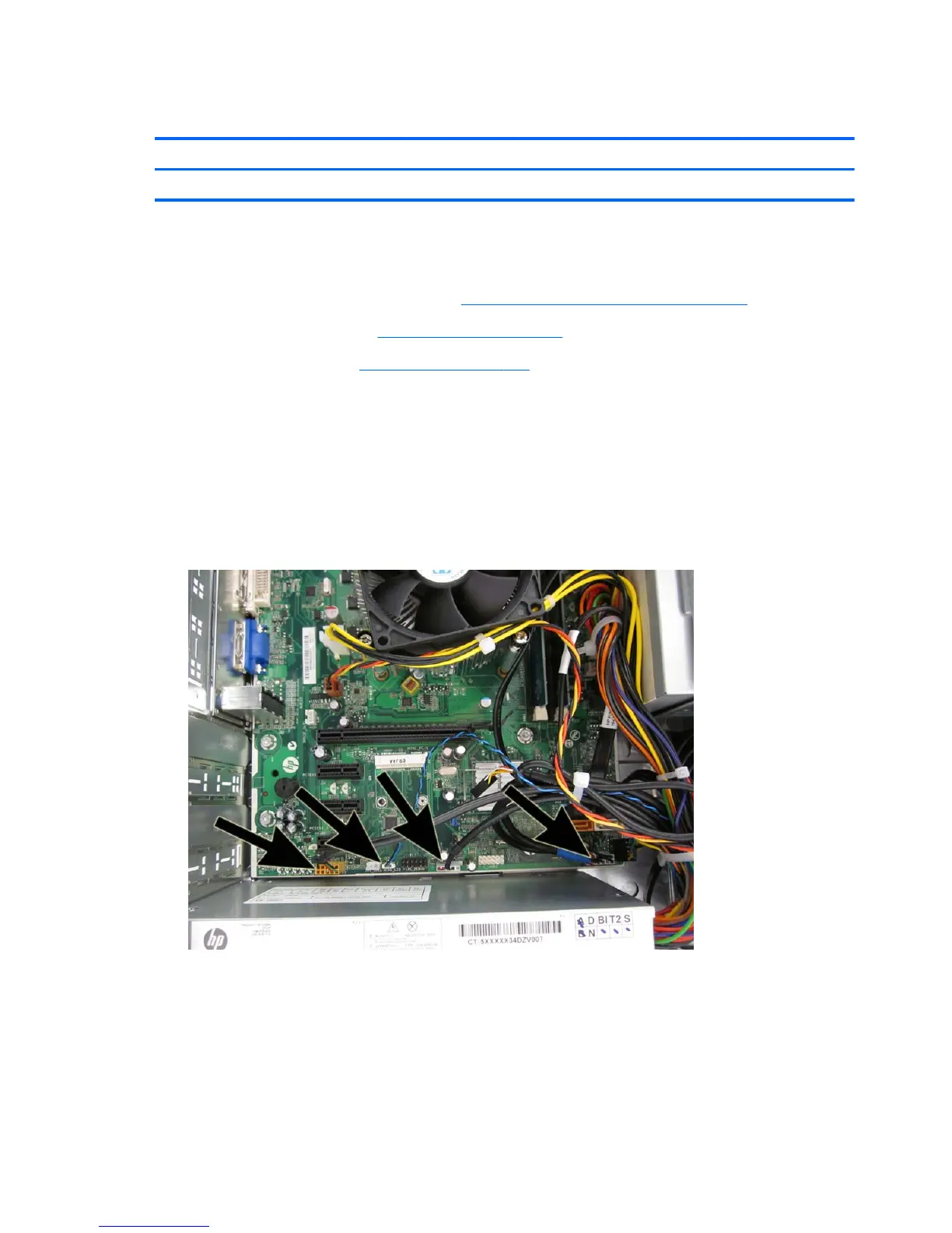
4. Disconnect the four cables from the system board as follows:
Yellow connector labeled F_AUDIO
White connector labeled MINI_LED
White connector labeled F_USB3
Black connector labeled F_USB2
Figure 8-27 Disconnecting the front I/O cables
126 Chapter 8 Removal and Replacement Procedures Small Form Factor (SFF) Chassis

Table of Contents

Questions and Answers:

Question and Answer IconNeed help?

Do you have a question about the HP Elite 7500 Microtower and is the answer not in the manual?

HP Elite 7500 Microtower Specifications

General IconGeneral
Form FactorMicrotower
ProcessorIntel Core i5 or i7 (varies by model)
RAMUp to 32 GB
StorageUp to 2 TB HDD or 256 GB SSD
GraphicsIntegrated Intel HD Graphics or optional discrete graphics
Optical DriveDVD-ROM
AudioHigh Definition Audio
NetworkingGigabit Ethernet
PortsUSB 2.0, USB 3.0, Audio In/Out, VGA, DisplayPort
Operating SystemWindows 7 Professional
Power Supply300W
Expansion Slots1 PCIe x16, 1 PCIe x1, 1 PCI

Related product manuals