EasyManuals Logo

HP Elite 7500 Microtower User Manual

HP Elite 7500 Microtower
230 pages
To Next Page IconTo Next Page
To Previous Page IconTo Previous Page
Page #126 background imageLoading...
Page #126 background image
Cable Connections
System board connectors are color-coded to make it easier to find the proper connection.
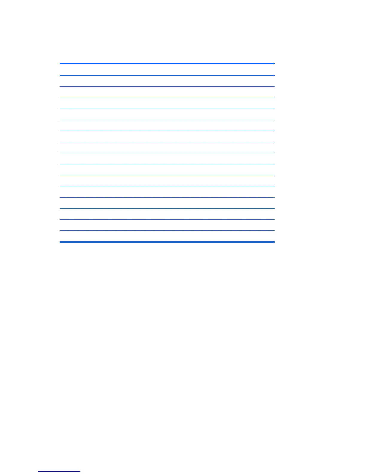
Connector Name Connector Color Description
ATX_POWER white Power supply, 24-pin
ATX_CPU white Power supply, 4-pin
SYS_FAN brown Chassis fan
CPU_FAN white Heat sink fan
INT_SPKR white Speaker
F_PANEL black Power switch
F_AUDIO yellow Front I/O audio
MINI_LED white Front_I/O
F_USB1 white Media card reader
F_USB2 white Front I/O USB
F_USB3 white Front I/O USB
SATA1 dark blue Primary hard drive
SATA2 white Primary optical drive
SATA3 light blue Second hard drive
SATA4 orange Second optical drive
116 Chapter 8 Removal and Replacement Procedures Small Form Factor (SFF) Chassis

Table of Contents

Questions and Answers:

Question and Answer IconNeed help?

Do you have a question about the HP Elite 7500 Microtower and is the answer not in the manual?

HP Elite 7500 Microtower Specifications

General IconGeneral
Form FactorMicrotower
ProcessorIntel Core i5 or i7 (varies by model)
RAMUp to 32 GB
StorageUp to 2 TB HDD or 256 GB SSD
GraphicsIntegrated Intel HD Graphics or optional discrete graphics
Optical DriveDVD-ROM
AudioHigh Definition Audio
NetworkingGigabit Ethernet
PortsUSB 2.0, USB 3.0, Audio In/Out, VGA, DisplayPort
Operating SystemWindows 7 Professional
Power Supply300W
Expansion Slots1 PCIe x16, 1 PCIe x1, 1 PCI

Related product manuals