Reverse this procedure to install thedisplay panel.
Power connector cable
To remove the power connector cable, use this procedure and illustration.
Table 5-9 Power connector cable description and part number
Description Spare part number
Power connector cables
For 150 W models N13377-001
For 200 W models N13378-001
Before removing the power connector cable, follow these steps:
1. Prepare the computer for disassembly (see Preparation for disassembly on page 33).
2. Remove the bottom cover (see Bottom cover on page 33).
3. Remove the battery (see Battery on page 34).
4. Remove the heat sink (see Heat sink on page 40).
5. Remove the fan assembly (see Fan assembly on page 41).
6. Remove the display panel assembly (see Display assembly panel on page 43).
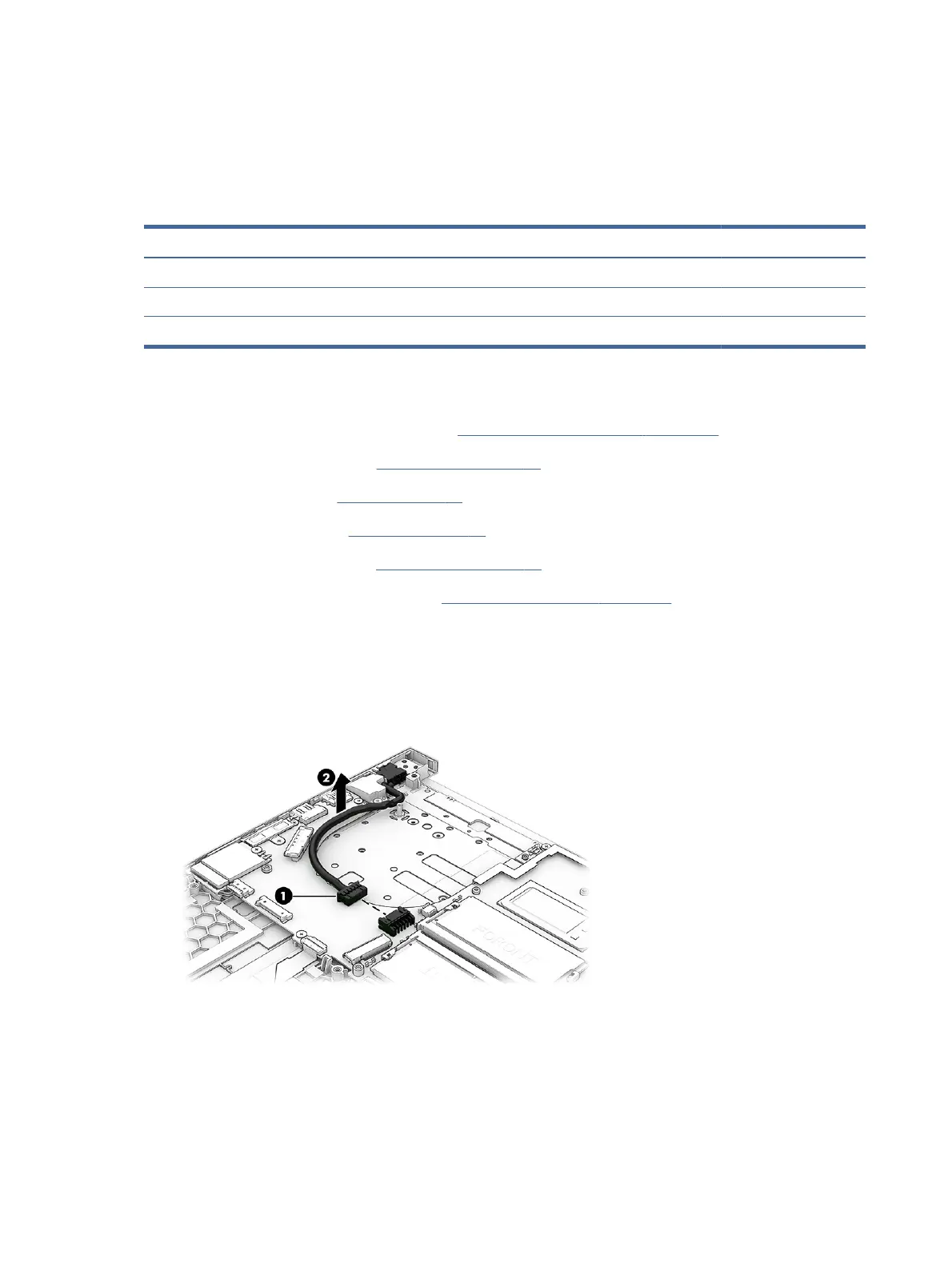
Remove the power connector cable:
1. Make sure the power connector cable from the system board is disconnected (1).
2. Remove the power connector cable from the computer (2).
Reverse this procedure to install the power connector cable.
System board
To remove the system board, use these procedures and illustrations.
44
Chapter 5Removal and replacement procedures for authorized service provider parts

 Loading...