30
Connecting the IRF member switches in one rack
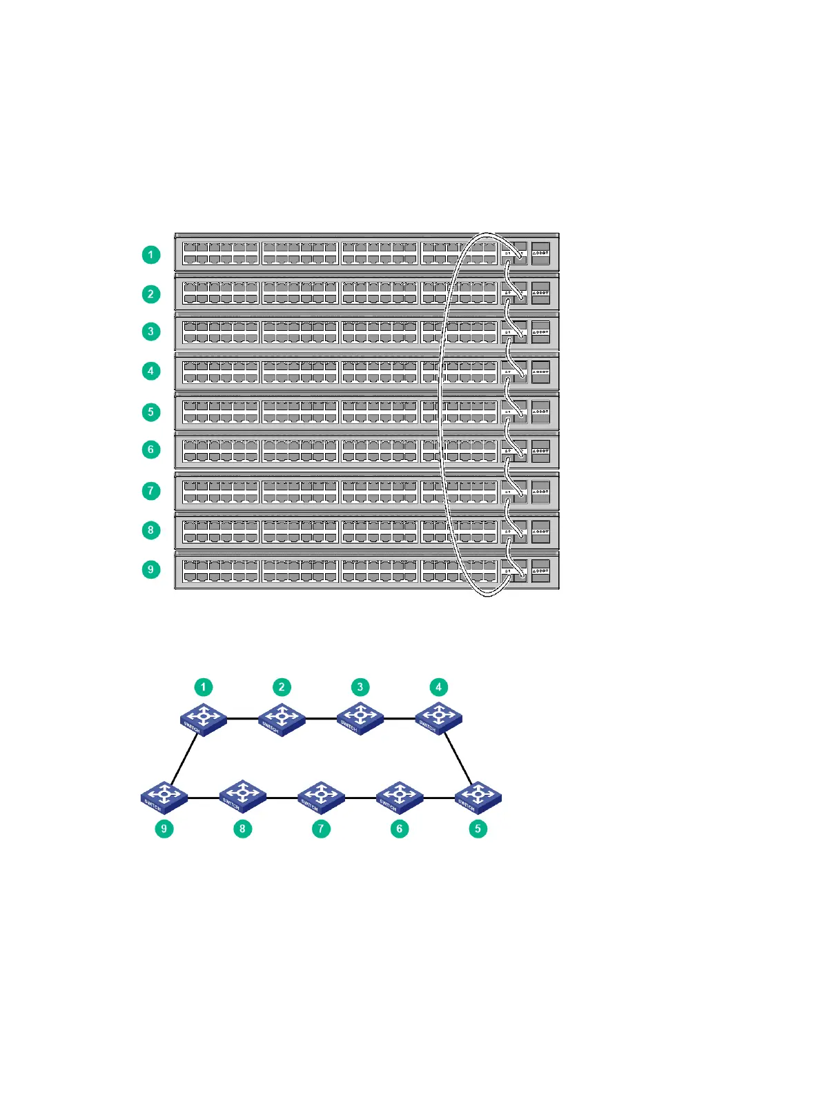
Use SFP+ cables to connect the IRF member switches (9 switches in this example) in a rack as
shown in Figure 25. The switches in the ring topology (see Figure 26) are in the same order as
connected in the rack.
Figure 25 Connecting the switches in one rack
Figure 26 IRF fabric topology
Connecting the IRF member switches in a ToR solution
You can install IRF member switches in different racks side by side to deploy a top of rack (ToR)
solution.
Figure 27 shows an example for connecting 9 top of rack IRF member switches by using
SFP+/QSFP+ transceiver modules and optical fibers. The topology is the same as Figure 26.
 Loading...