Rack options 19
9.
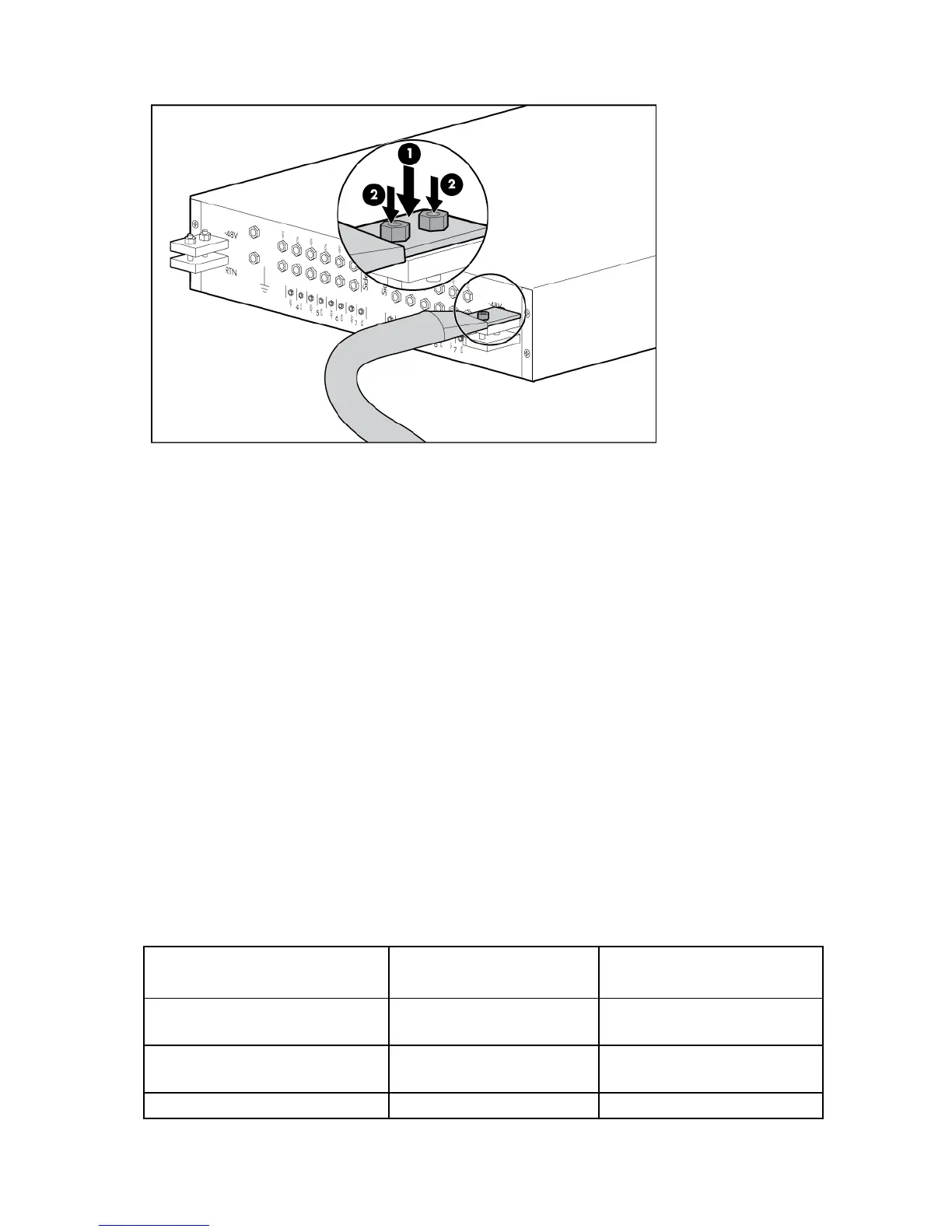
Connect the site input power cables to the input busbar studs.
a. Connect the -48V/-60V red wire to the top busbar on each Side (A & B).
b. Connect the RTN black wires to the bottom busbar on each Side (A & B).
c. Use the 14mm socket wrench to reinstall the nuts over the lugs.
10. From the front, pull the breaker panel forward, reattach the front mounting brackets, and then secure
the breaker panel to the front cage nuts.
11. From the rear, reconnect the ground strap with the ground strap M6 connection hardware, and then
reattach the rack identification panel, routing the site input power cables behind it.
12. Reinstall the breaker panel rear cover.
Connecting the breaker panel to the power supplies
The HP BladeSystem Breaker Panel contains six red source -48 DC volt cables and six black return cables.
The ends of each cable are labeled with the location, which describe where to connect the cable to the
breaker panel and to the DC input module.
The DC cables are labeled as follows:
• BP—Breaker panel
• E—Enclosure
• PSx—Power supply and number
• A—Breaker panel Side A
• B—Breaker panel Side B
Cable Breaker Panel End
(90° Lug)
Input Module End
(45° Lug)
Red source -48 DC or Black return BP-A1
(E-PS1)
(E-PS1)
BP-A1
Red source -48 DC or Black return BP-A2
(E-PS2)
(E-PS2)
BP-A2
Red source -48 DC or Black return BP-A3 (E-PS3)
 Loading...


