Rack options 20
Cable Breaker Panel End
(90° Lug)
Input Module End
(45° Lug)
(E-PS3) BP-A3
Red source -48 DC or Black return BP-B1
(E-PS4)
(E-PS4)
BP-B1
Red source -48 DC or Black return BP-B2
(E-PS5)
(E-PS5)
BP-B2
Red source -48 DC or Black return BP-B3
(E-PS6)
(E-PS6)
BP-B3
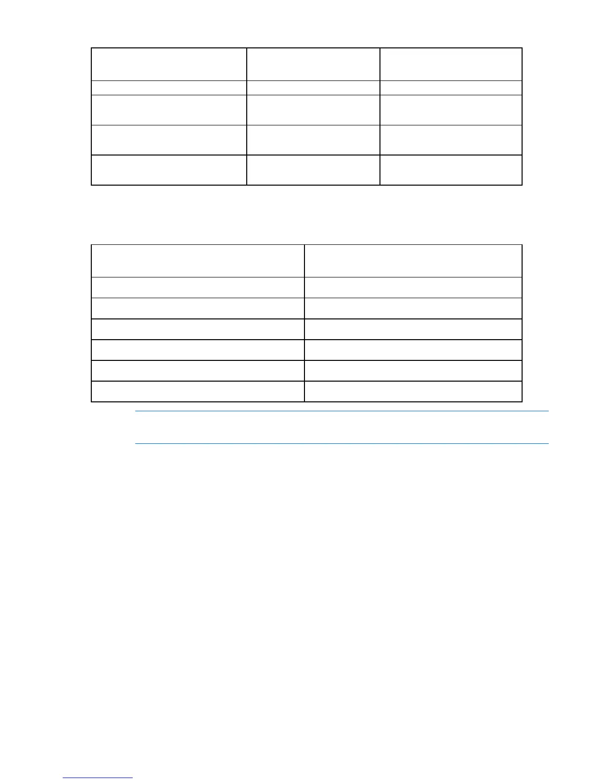
Use the following DC cable connection configuration table to connect the DC power cables to the breaker
panel and to the DC input module.
Each of these connections is a pair of wires, one for -48V DC and one for return.
Breaker Panel DC Input Module
(Power and return)
Enclosure power supply
A1 red source / A1 black return PS1
A2 red source / A2 black return PS2
A3 red source / A3 black return PS3
B1 red source / B1 black return PS4
B2 red source / B2 black return PS5
B3 red source / B3 black return PS6
NOTE: Remove the rack side panels for easier cable routing, if necessary. For more
information, see the documentation that ships with the rack.
To connect cables to the breaker panel:
1. Referring to the DC cable connection configuration table, connect a red source -48 DC volt cable to
the left side of the A1 position with a 90° lug.
 Loading...


