Removal and replacement procedures 34
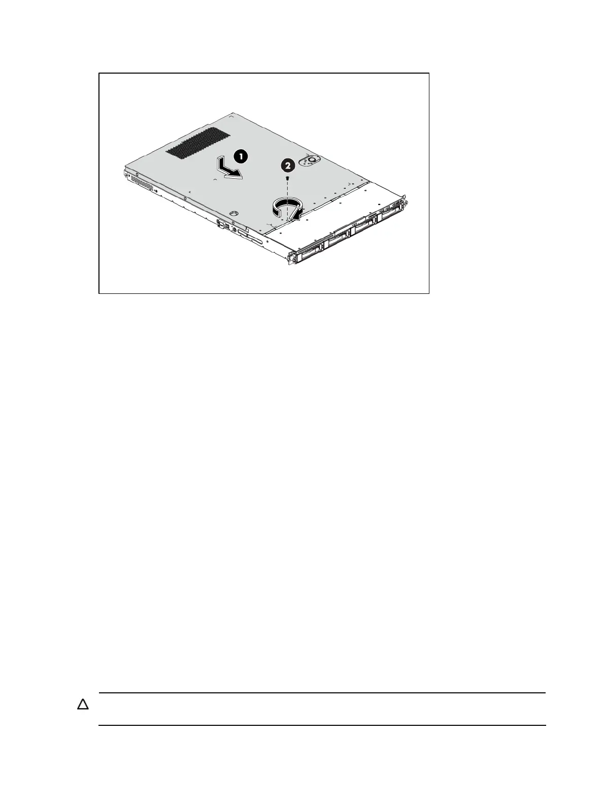
Figure 2 Reinstalling the Top Cover
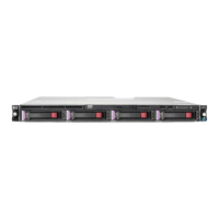
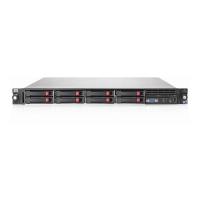
Drives
The server supports 5 to 9 drive bays --- 4 drive bays for 3.5 in. LFF hard disk drives and 1 drive bay
for an optical disc drive, or 8 drive bays for 2.5 in. SFF hard disk drives and 1 drive bay for an
optical disc drive.
Cable management
Always follow good cable management practices when working inside the computer.
• Keep cables away from major heat sources like the heat sink.
• Do not jam cables on top of expansion cards or memory modules. Printed circuit cards are not
designed to withstand excessive pressure.
• Keep cables clear of sliding or moveable parts to prevent cutting or crimping.
• When folding a flat ribbon cable, never fold to a sharp crease. Sharp creases may damage the
wires.
• Some flat ribbon cables come pre-folded. Never change the folds on these cables.
• Do not sharply bend any cable. A sharp bend can break the internal wires.
• Never bend a SATA data cable tighter than a 30 mm (1.18 in.) radius.
• Never crease a SATA data cable.
• Do not rely on components like the drive cage, power supply, or system cover to push cables
down into the chassis.
The next steps illustrate the removal of power cable from connector J52, 53 and 54 on system board.
1. Squeeze on the top of the retaining latch attached to the cable end of the connector.
2. Grasp the cable end of the connector and pull it straight up.
CAUTION: Always pull the connector—NEVER pull on the cable. Pulling on the cable could damage
the cable and result in a failed power supply.
 Loading...