Removal and replacement procedures 36
Table 7 Cable Connections from the System Board
Cable To System Board Designator
20-pin front panel connector Front panel J98
Front panel USB 2.0 port Front panel USB 2.0 J8
SD card USB 2.0 port SD reader module J81
Internal USB 2.0 port Internal USB cable kit J49
24-pin power connector Power supply J52
8-pin power connector Power supply J53
4-pin power connector Power supply J54
3-pin backplane I
2
C connector Backplane J68
16-pin power backplane control connector Power supply J55
6-pin system fan 1 connector System fan 1 J61
6-pin system fan 2 connector System fan 2 J62
6-pin system fan 3 connector System fan 3 J63
6-pin system fan 4 connector System fan 4 J64
6-pin system fan 5 connector System fan 5 J65
6-pin system fan 6 connector System fan 6 J66
6-pin system fan 7 connector System fan 7 J69
Table 8 Drive Cable Connections / 4 3.5” LFF Hot-plug HDD Model
Cable To System Board Designator
Mini-SAS connector for SATA Backplane J13
Table 9 Drive Cable Connections / 8 2.5” SFF Hot-plug HDD Model
Cable To System Board Designator
PCI storage controller card (LP) 8 2.5” SFF HDD backplane 3
rd
party mini SAS
connector
PCI storage controller card (LP) 8 2.5” SFF HDD backplane 3
rd
party mini SAS
connector
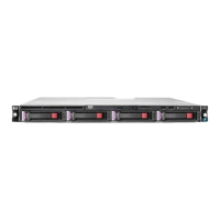
Drive bay configuration
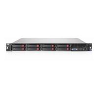
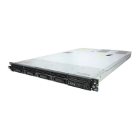
The server supports a maximum of 5 to 9 drive bays --- 4 drive bays for 3.5 in. LFF hard disk drives
and 1 drive bay for 9.5mm (0.37 in.) optical disc drive, or 8 drive bays for 2.5 in. SFF hard disk
drives and 1 drive bay for 9.5mm (0.37 in.) optical disc drive.
 Loading...