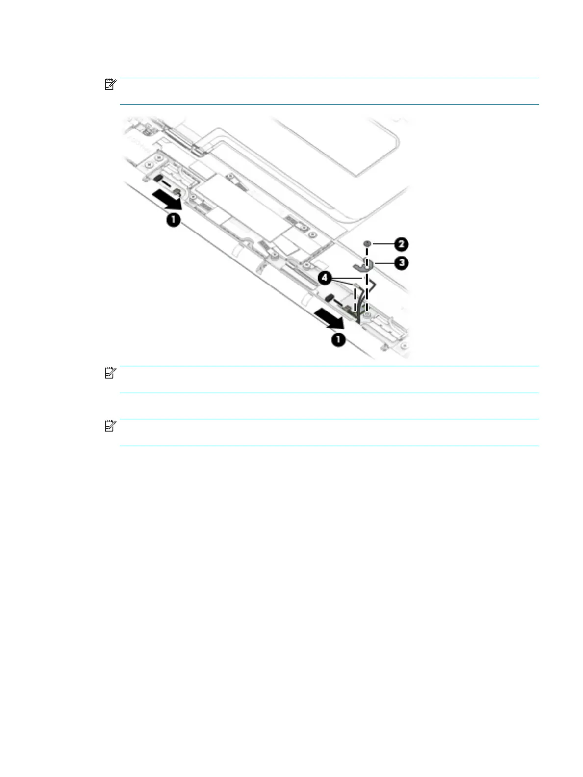
4. Disconnect the WLAN antenna cables (4) from the WLAN module built onto the system board.
NOTE: The #1/white WLAN antenna cable connects to the WLAN module "#1/Main" terminal. The #2/
black WLAN antenna cable connects to the WLAN module "#2/Aux" terminal.
NOTE: The rubber screw covers removed in the following step are dierent in size and shape. Make note
of which rubber screw cover was removed from which cavity.
5. Remove the rubber screw covers (1) that conceal the speaker assembly screws.
NOTE: The rubber screw covers are included in the Mylar/Rubber/Tape Kit, spare part number
L38695-001.
6. Remove the two Phillips M2.0×3.4 screws (2) that secure the speaker assembly to the display back cover.
Component replacement procedures 47