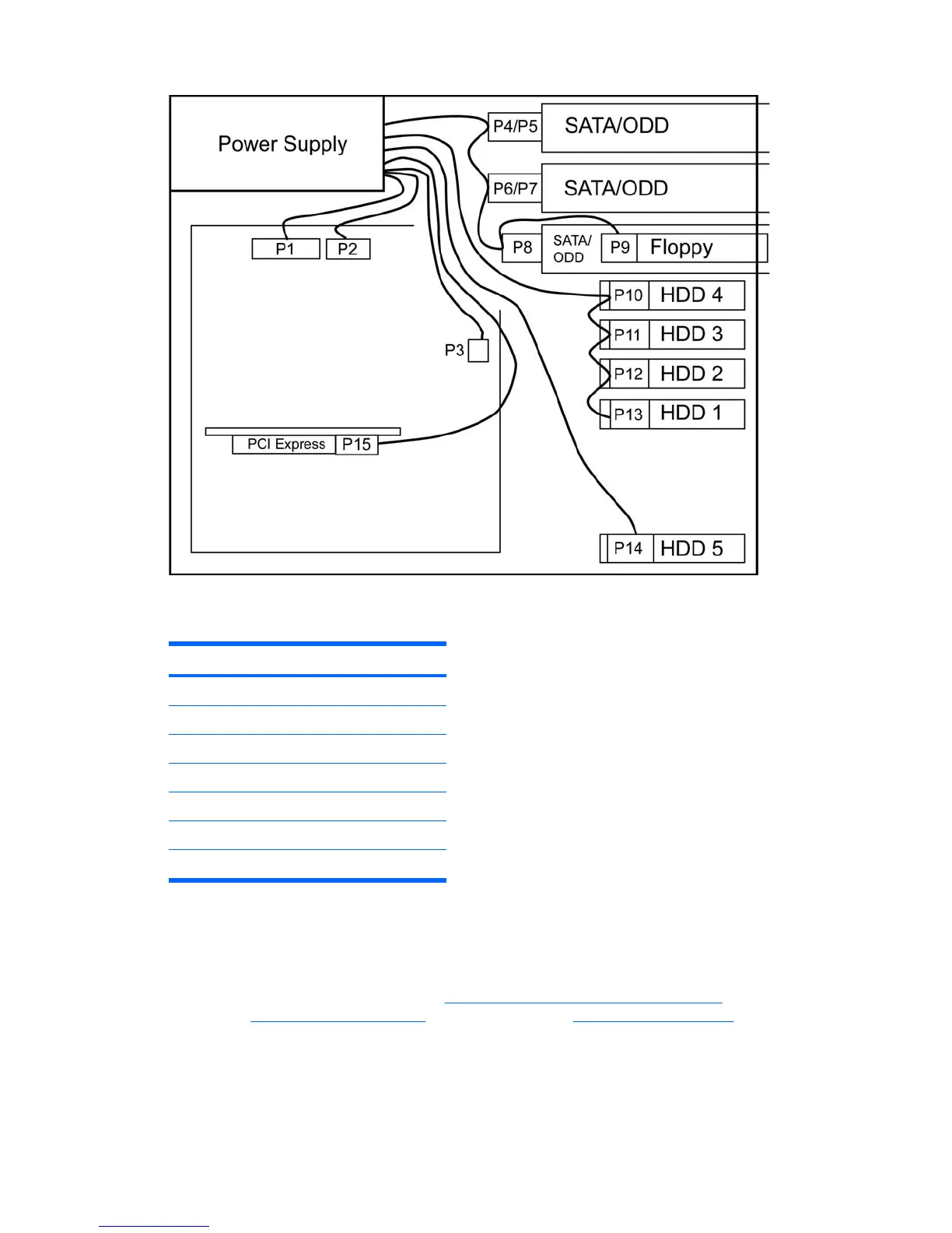
Figure 4-27 Identifying correct power connections
Table 4-7 Power connector descriptions
Connector Description
P1 24–pin Power Connector
P2 4–pin Memory Connector
P3 8–pin CPU0 Connector
P4–P8 HDD/Optical Connector
P9 Diskette Connector
P10–P14 HDD Connector
P15 PCI-E Connector
Optical drive
Your workstation might have a SATA or an IDE optical drive. To remove the optical drive.
1. Disconnect power from the system (
Pre-disassembly procedures on page 53). Remove the access
panel (
Access panel on page 58) and the front bezel (Front bezel on page 59).
ENWW Removing and replacing components 77
 Loading...