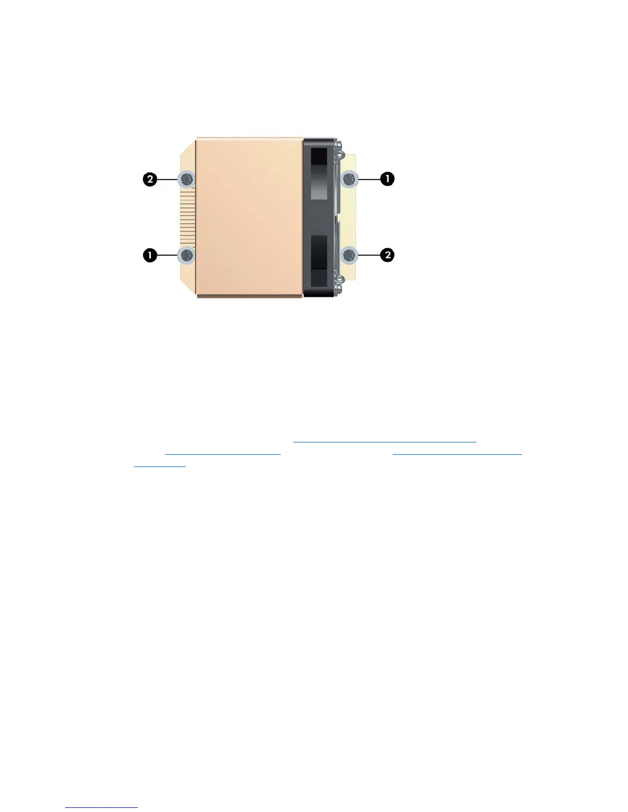
4. Insert and tighten the four CPU heatsink screws. First, tighten all of the screws partially so that the
CPU heatsink remains level. Next, fully tighten one pair of diagonally opposite screws (1), and then
fully tighten the remaining pair (2). Tighten firmly to a torque setting of 6 in-lb.
Figure 4-46 Identifying proper screw removal order
5. Connect the CPU heatsink fan connector to the system board (2) as shown in Figure 1–45.
Processor
Removing the processor
1. Disconnect power from the system ( Pre-disassembly procedures on page 53). Remove the access
panel (
Access panel on page 58) and the CPU heatsink (Removing the CPU heatsink
on page 86).
ENWW Removing and replacing components 89