Thermal sensors
The following illustration shows the locations of the thermal sensors. Sensors that attach with a harness
can be replaced.
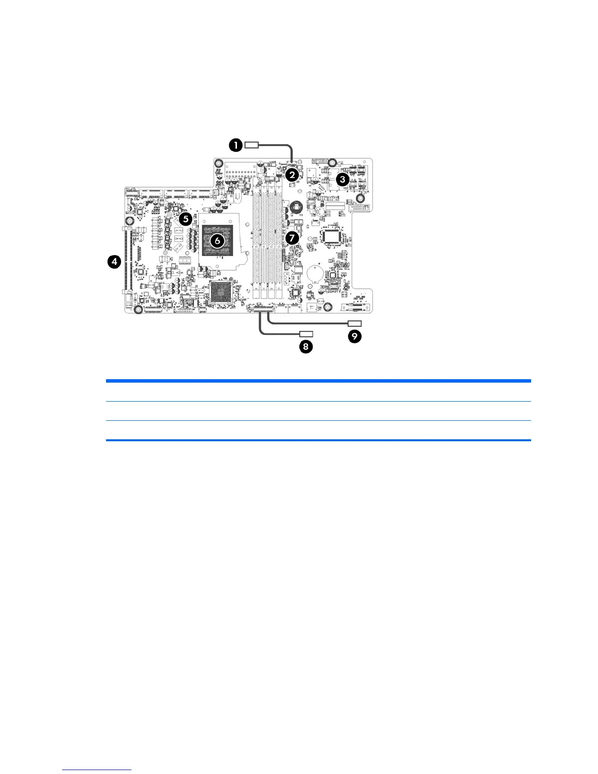
Figure 3-2 Thermal sensor locations
Table 3-2 Thermal sensor descriptions
1 Outlet air sensor 4 MXM GPU sensor 7 Memory VR sensor
2 12V-3.3V VR sensor 5 CPU0 VR sensor 8 Hard disk drive sensor
3 Backlight VR sensor 6 CPU0 DTS sensor (inside processor) 9 Inlet air sensor
Component replacement guidelines
53
 Loading...