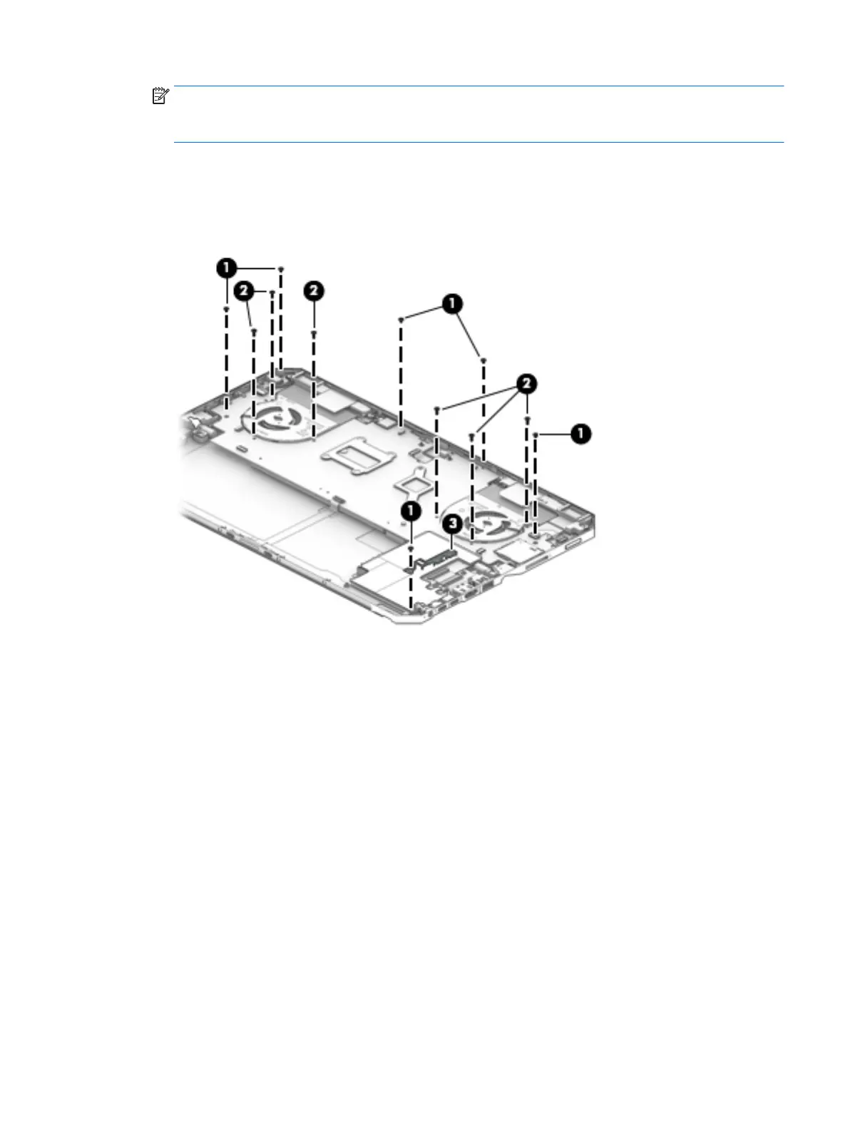
NOTE: The quantity of screws removed in step 6 varies depending on tablet model. Tablet models
equipped with a graphics subsystem with discrete memory have six screws. Tablet models equipped with a
graphics subsystem with UMA memory have three screws.
6. Remove the six (or three, depending on computer model) Phillips M2.0×5.6 screws (2) that secure
the system board to the back cover.
7. Remove the support bracket (3).
The support bracket is available in the Bracket Kit, spare part number L03254-001.
8. Eject the smart card reader slot blank (1).
The smart card reader slot blank is available using spare part number L03261-001.
9. Lift the right side of the system board (2) until it rests at an angle.
Component replacement procedures 49
 Loading...