5 Installation and commissioning
HSD S.p.A. © - h0104k01a.fm291119
43
High node address bit settings
Servo-motor SM137D enables you to set an address between 1 and 127:
Node-ID = (A0 * 1) + (A1 * 2) + (A2 * 4) + (A3 * 8) + (A4 * 16) + (A5 * 32) + (A6 * 64)
However, the range of addresses that can be set is usually limited to the range [1...31], which
corresponds to the bit address [A0...A4], since only switches 1 to 5 are available to set the address.
In order to also set address bits A5 and A6, you must start the device with switch 5 and 6 On,
switch 1 Off and switches 2 and 3 set according to the desired address, as shown in the table
below.
Switch on the servo-motor and wait until the operation has been completed. The green LED will
flash with the code shown in the paragraph “Transmission speed setting (bit-rate)” on page 42,
indicating storage of the two high bits.
At the end of the procedure the servo-motor must be turned off and the dip-switch configuration
restored.
Resetting the default parameters
To restore all the factory settings, including the bit-rate value and the two high bits in the address,
with the power supply to the servo-motor cut, set switches 1, 5 and 6 to On (DSW2).
Connect the logic supply. The green LED will flash with the code shown in the paragraph
“Transmission speed setting (bit-rate)” on page 42, indicating that the default settings have been
restored.
At the end of the procedure the servo-motor must be turned off and the dip-switch configuration
restored.
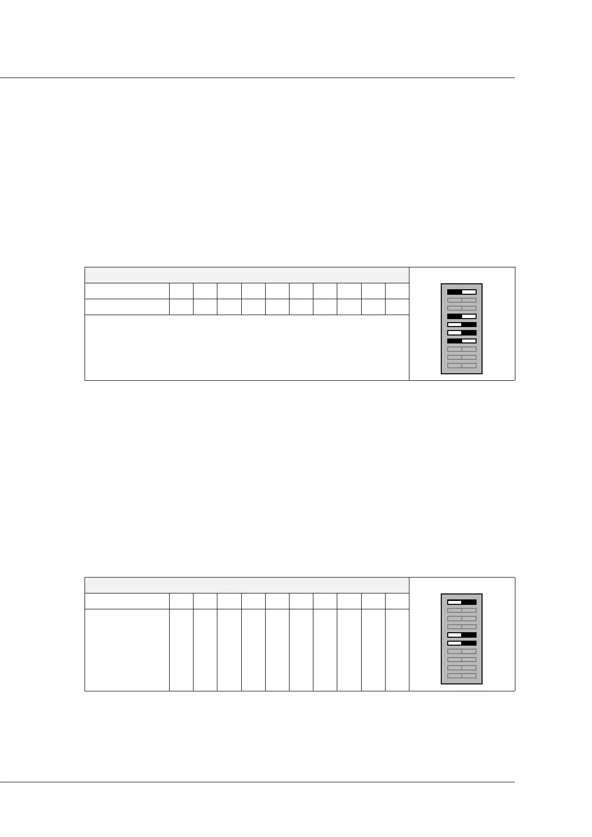
DSW2
Switch 12345678910
Position Off A5 A6 X On On ----
A5 and A6 = high bits of the node number
DSW2
Switch 12345678910
Position On XXXOn On ----