5 Installation and commissioning
30
HSD S.p.A. © - h0104k01a.fm291119
5.4 Mechanical connections
The load-bearing structure, on which the product is to be mounted, must be sufficiently rigid to
support the weight and type of machining to be carried out.
Fixing
To fix the servo-motor on the user machine, use the 2 free holes on the clamping flange (ref. D,
page 24). M6 or M5 screws can be used.
Use 2 M6 screws, minimum strength class 8.8.
Choose a screw length that ensures they are inserted in the flange by at least 8mm but not more
than 10mm.
Alternatively, use two M5 galvanised screws (minimum strength class 8.8).
Choose a screw length that ensures they are inserted in the flange by at least 20mm but not more
than 22mm, and are screwed in by at least 8mm.
To ensure the necessary electrical conductivity, use galvanised screws only.
Tightening torque of the screws
M6 screws = 9 Nm
M5 screws = 6 Nm
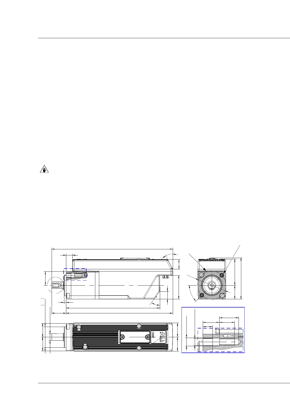
Overall dimensions
More information about fixing can be found in appendix A “Technical characteristics”.
O 10
-0.008
-0.013
O 30 h7
0
-0,021
2020
20,420,4
A
3
135,7
154,421
(175,4 )
3
5
°
20
9,1
2
8
°
14
11,1
34,5
3820
4
1
O
4
5
°
59,9
DETTAGLIO /DETAIL B
n.2 fori M6
n.2 M6 holes
7
12 11
14
n.2 fori M5
n.2 M5 holes
B
DETAIL B
B
Clamping flange
2 fixing holes