5 Installation and commissioning
44
HSD S.p.A. © - h0104k01a.fm291119
5.8.4 RS-485 configuration
Access the dip-switches of the electronic device tab, as explained on page 35.
The servo motor communication protocol can be selected using dip-switch DSW1.
Only change the configuration of the dip-switches when the board is not powered up.
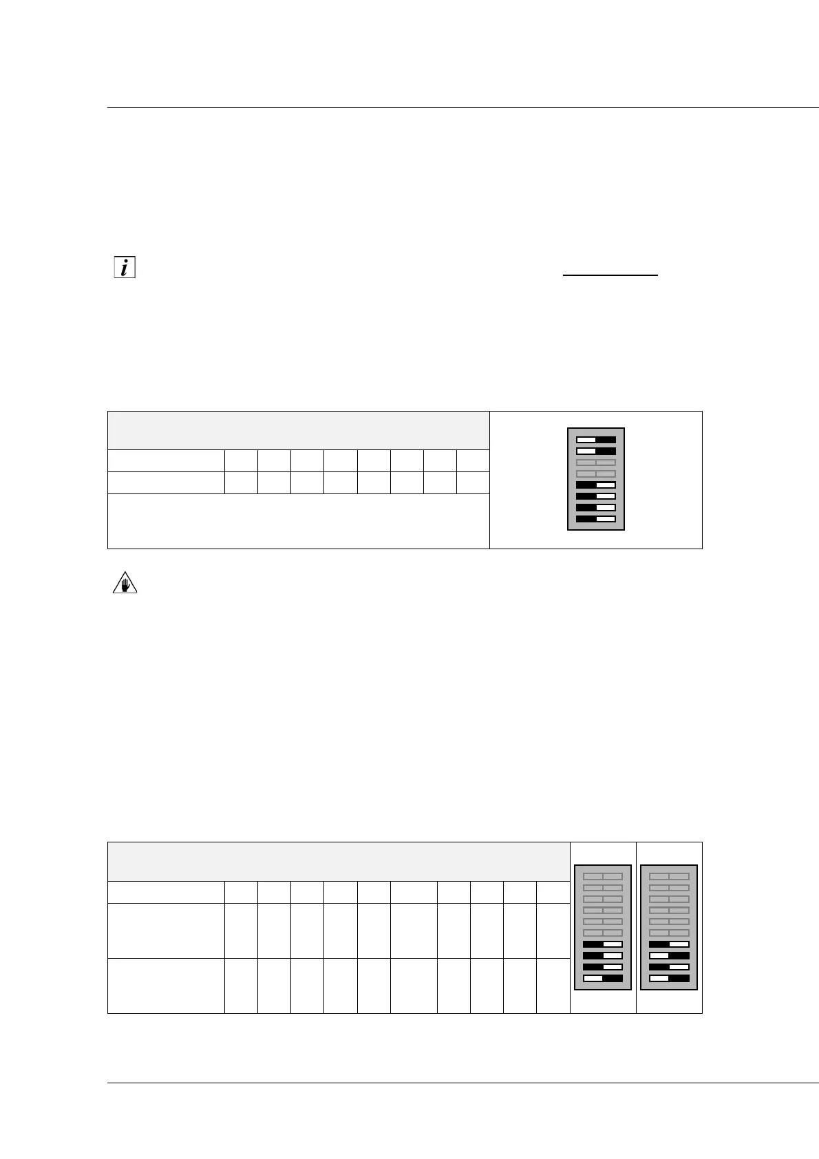
Dip-switch DSW1
To set the RS-485 protocol on the servo-motor, configure the DSW1 switches as shown below.
Switches 3 and 4 are used to terminate the line, which is necessary to avoid signal flip phenomena
on the line.
If switches 3 and 4 are set differently (for example 3 ON and 4 OFF), the module may
not work correctly.
Dip-switch DSW2
The five addressing switches (A0-A4) are used to set the address on the servo-motor Fieldbus. To
set the servo-motor address, enable the switches in such a way that the binary number
corresponds to the required address. Bear in mind that the least important address bit is A0, and
the most important is A4.
Switch 6 is used to set the communication speed which, in the case of the RS-485 protocol, can be
set at 38400 bit/s (ON) or 9600 bit/s (OFF).
Switches 7, 8, 9 and 10 are used to select the servo-motor operating mode and its compatibility
with previous versions, in the event of a replacement.
To do this, refer also to paragraph 5.8.1 “Configuration following a replacement”.
DSW1
Switch 12345678
Position On On T T Off Off Off Off
T = Fieldbus line termination:
set Off if the Fieldbus continue,
set On at the Bus termination.
DSW2
Switch 12345 6 78910
SM 137 D
standard
mode
A0 A1 A2 A3 A4
bit-
rate*
*
Rapid setting of transmission protocol RS-485: ON = 38400 bit/s, OFF = 9600 bit/s.
Off Off Off On
Mode
compatible with
SM 137 C
A0 A1 A2 A3 A4
bit-
rate*
Off On Off On