5 Installation and commissioning
HSD S.p.A. © - h0104k01a.fm291119
39
CANopen node address setting
Switches 1 to 5 (DSW2) set the servo-motor CANopen node address; in particular switch n°5
corresponds to the most significant address bit A4, and switch n°1 corresponds to the least
significant address bit A0.
All 31 combinations between 1 and 31 are allowed.
Should it be necessary to set a node address higher than 31 (bits A5 and A6), please refer to
paragraph “High node address bit settings” on page 43.
The table below is given as an example with some address settings.
Examples:
Two devices on the same Fieldbus line cannot have the same address.
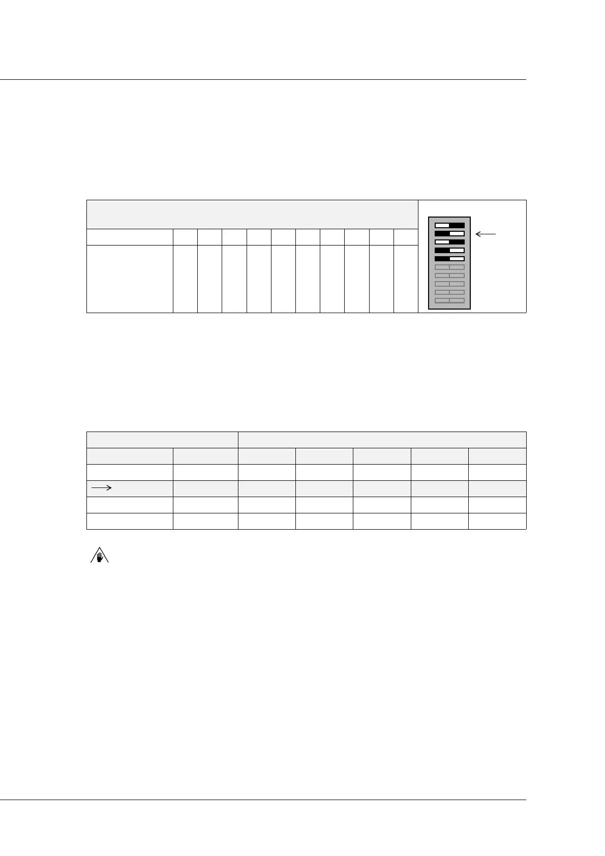
DSW2
Switch 12345678910
Address A0 A1 A2 A3 A4 - - - - -
ADDRESS DIP-SWITCH SETTING (from 5 to 1 DSW2)
Decimal Binary A4 A3 A2 A1 A0
01 00001 OFF OFF OFF OFF ON
05 00101 OFF OFF ON OFF ON
10 01010 OFF ON OFF ON OFF
21 10101 ON OFF ON OFF ON
10
9
8
7
6
5
4
3
2
1
10
9
8
7
6
5
4
3
2
1
DSW2
Decimal: 05
like the
example in the
table below